Optical shutter for miniature cameras

a miniature camera and optical shutter technology, applied in the field of optical shutters for miniature cameras, can solve the problems of inability to hold and store signals, image artifacts, complex mechanical structure, etc., and achieve the effect of increasing the operating speed of the shutter, wide active area, and increasing the shutter operating speed

Active Publication Date: 2008-09-23
CORE WIRELESS LICENSING R L
View PDF19 Cites 7 Cited by
  • Summary
  • Abstract
  • Description
  • Claims
  • Application Information

AI Technical Summary

Benefits of technology

[0033]The fluid is introduced to the capillary space through at least one fluid duct which is opposite the active area of the interface. Because the fluid duct is opposite the active area, the traveling distance required for the fluid to completely cover the active area may be substantially shorter than the width of the active area. This increases the operating speed of the shutter.
[0034]In an embodiment, the shutter may comprise several adjacent fluid ducts to further increase the operating speed of the shutter and / or to implement a wide active area.
[0036]The light rays which form the image do not pass through the capillary space, which helps to minimize the distortion of the acquired image. The direction of the light rays is changed upon total internal reflection, which allows implementation of compact and slim optical systems. Only reflected light rays are used for imaging purposes, and the space behind the shutter may be used for further components of a portable device. The moving mass of the fluid may be very small, and, consequently, the vibration and acoustic noise generated during the shutter operation are low. Also the power consumption is very low.

Problems solved by technology

A typical low-cost image sensor does not comprise charge shift registers and it cannot hold and store the signals.
This may lead to a distortion of the recorded image, image artifacts, especially when the camera or the target is moving.
Traditional mechanical global shutters exhibit several drawbacks, e.g. complex mechanical structure, large size and relatively high power consumption.
Therefore, mechanically implemented global shutters are not optimal for imaging systems integrated in small portable devices.

Method used


Image

  • Optical shutter for miniature cameras
  • Optical shutter for miniature cameras
  • Optical shutter for miniature cameras

Examples


Embodiment Construction

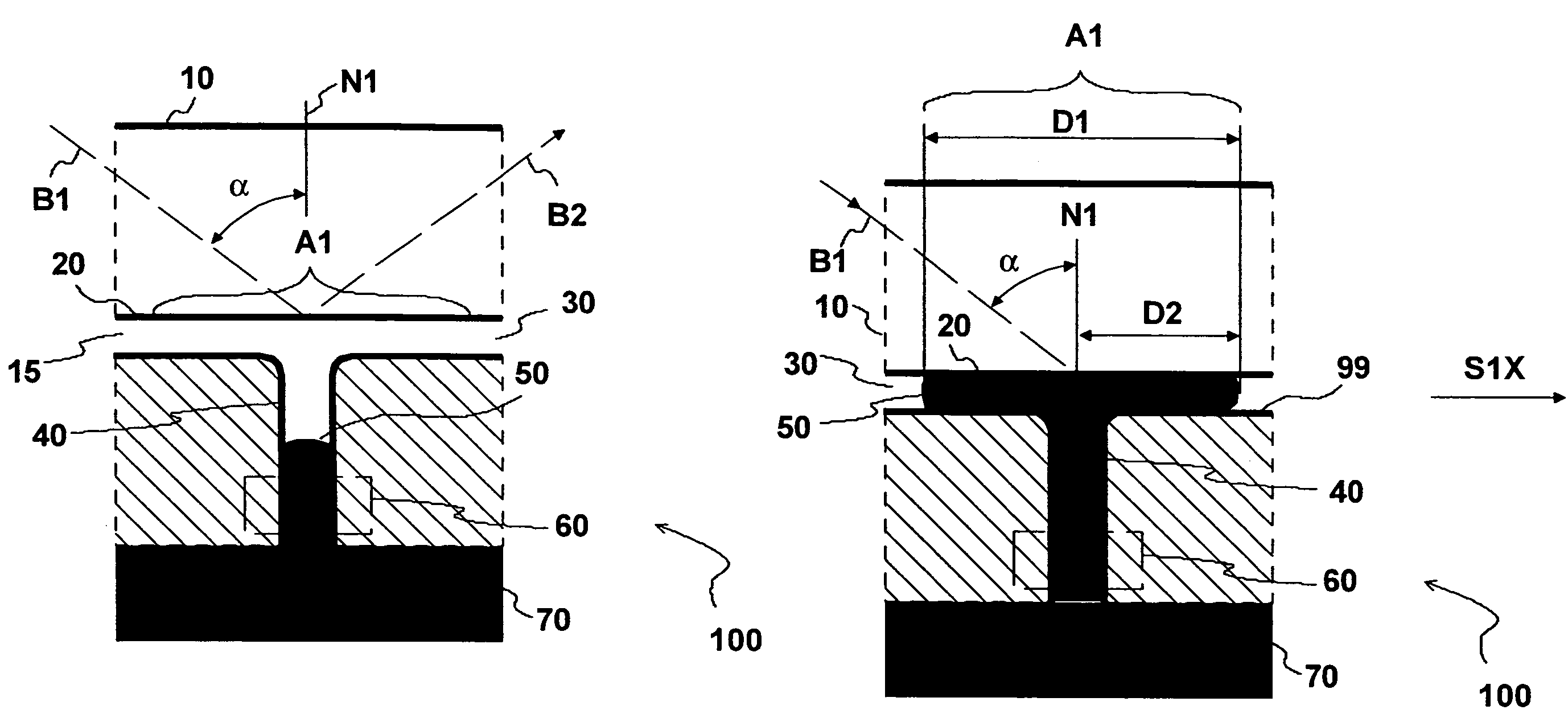
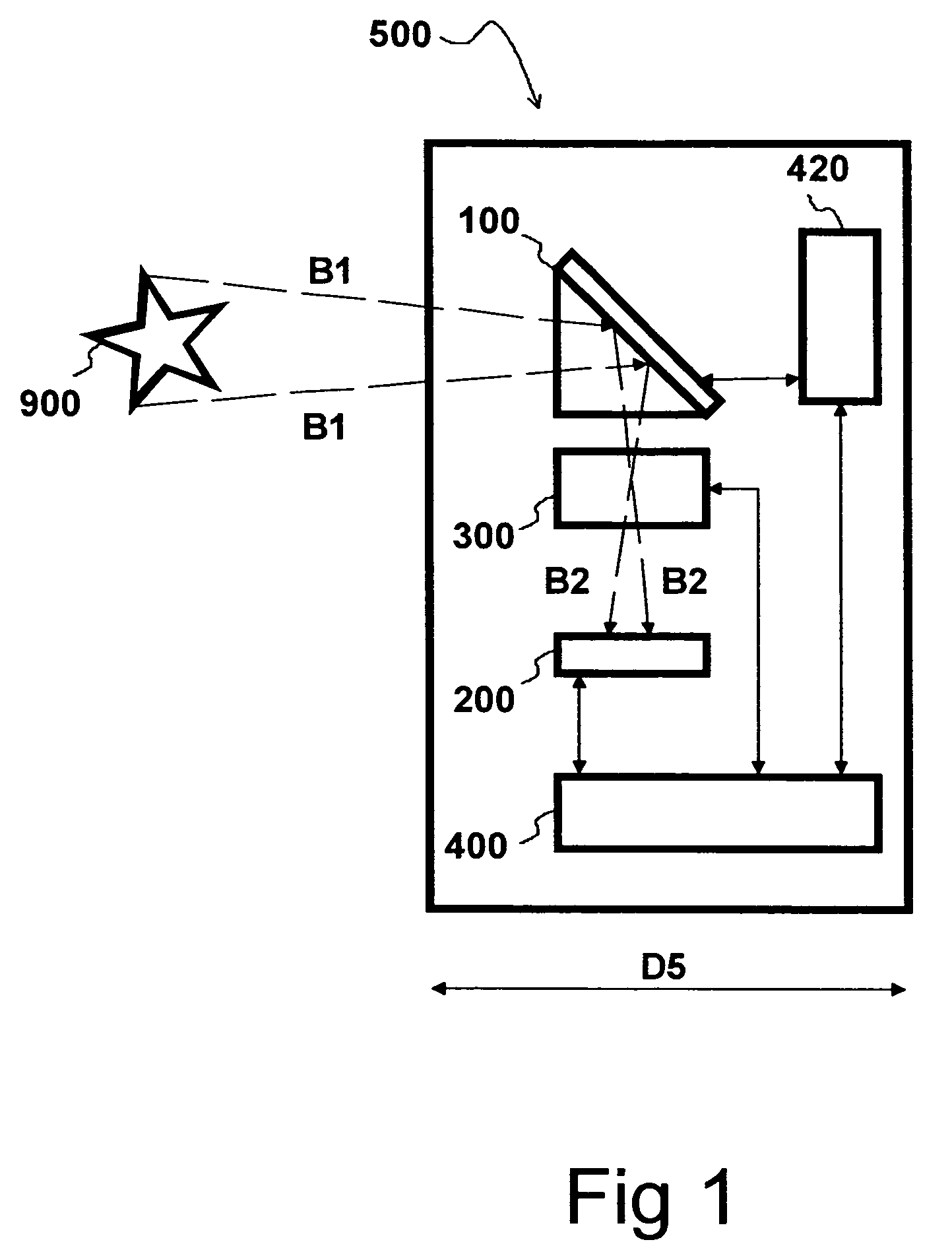
[0066]The optical device 500 shown in FIG. 1 comprises an imaging system. The imaging system comprises imaging optics 300 which are adapted to focus light rays B1 coming from a target 900 to an image sensor 200 to form an image of the target 900. The optical exposure of the image sensor 200 is at least partially defined by the shutter 100.

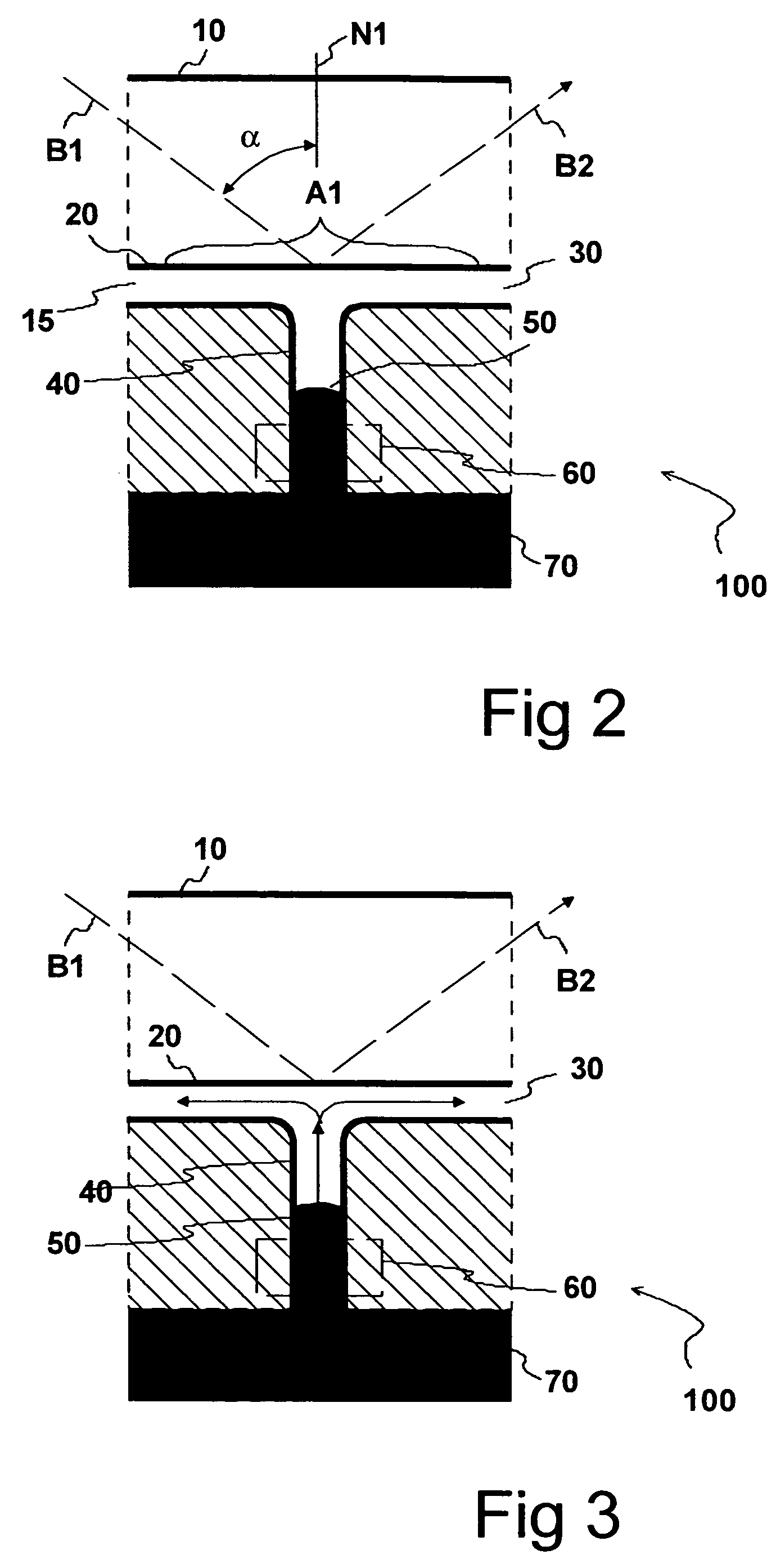
[0067]When the shutter 100 is set to a reflecting state, the reflected rays B2 are guided to the image sensor 200 through the imaging optics 300. When the shutter 100 is set to a non-reflecting state, the light rays B1 are absorbed in the shutter 100.

[0068]The imaging operation is at least partially controlled by a control unit 400, which directly or indirectly controls the focusing and the aperture of the imaging optics 300, the shutter 100 and the image sensor 200. The device 500 may further comprise a driver unit 420 to provide voltage amplification and / or digital-to-analog conversion of signals sent to the shutter 100.

[0069]The imaging optics 3...


PUM


Abstract

The invention relates to a shutter for an optical imaging system, e.g. a digital camera. The shutter comprises an interface between a transparent body and a capillary space. Light rays introduced to the active area of the interface are reflected by total internal reflection when the capillary space is filled with a gas. The light rays are transmitted through the interface when the capillary space is rapidly filled with a liquid. Thus, the light rays are either absorbed or reflected towards an image sensor, depending on the state of the shutter. The liquid is delivered to the capillary space through at least one duct which is positioned opposite the active area.

Description

FIELD OF THE INVENTION[0001]The present invention relates to the control of optical exposure times in optical imaging devices, e.g. in cameras.BACKGROUND OF THE INVENTION[0002]Digital cameras comprise imaging optics which are adapted to focus the image of a target onto an image sensor. The image sensor comprises an array of light sensitive pixels. The plurality of signals provided by the individual pixels constitute the digital image of the target. To the first approximation, a signal provided by each individual pixel is proportional to a time period between resetting or activation of said pixel and shifting of said signal (e.g. charge) to a shift register or to a memory.[0003]A typical low-cost image sensor does not comprise charge shift registers and it cannot hold and store the signals. Thus, when the reading of all signals can not take place simultaneously, the signals obtained from the individual pixels correspond to different time intervals. This may lead to a distortion of th...

Claims


Application Information

Patent Timeline
Patent Type & Authority Patents(United States)
IPC IPC(8): G01D5/34H01J1/56G03B9/08G03B9/00
CPCH04N5/2254G03B9/08G02B26/004G02B6/3538H04N23/55
Inventor LINKE, JORGRYYTTY, PASI
Owner CORE WIRELESS LICENSING R L
Why Eureka
Try Eureka