
Host computer system and storage system having a bandwidth management function for storage volumes

a storage volume and host computer technology, applied in the field of bandwidth management methods, can solve the problems of drop in access, inability to set the bandwidth according to the storage volume, and inability to set the access priority for each storage volum

Inactive Publication Date: 2008-09-23
GOOGLE LLC
View PDF10 Cites 11 Cited by
  • Summary
  • Abstract
  • Description
  • Claims
  • Application Information

AI Technical Summary

Benefits of technology

The patent describes a computer system that can manage the distribution of bandwidth (the amount of data transfer) to different storage volumes connected to a computer network. This is important because if multiple storage volumes are attached to the same port, the system can ensure that each volume has enough bandwidth to perform its tasks efficiently. The system includes a management computer that sends a request to set bandwidth for each storage volume to a control unit in the storage system. The control unit allocates the storage volume with the requested bandwidth to the host computer, ensuring optimal performance. Overall, this technology allows for better management of bandwidth and ensures the efficient use of storage space.

Problems solved by technology

However, in the case of the technology disclosed in JP 2005-209149 A, it is impossible to set a bandwidth according to the storage volume.
Thus, when it occurs, concentration of access to the mail data (storage volume) of January creates a problem of a drop in access to the mail data (storage volume) of March to which priority should be given.
However, when the mail data (storage volume) of January and the mail data (storage volume) of March are accessed from the same host computer, access priority cannot be set for each storage volume.

Method used


Image

  • Host computer system and storage system having a bandwidth management function for storage volumes
  • Host computer system and storage system having a bandwidth management function for storage volumes
  • Host computer system and storage system having a bandwidth management function for storage volumes

Examples


first embodiment

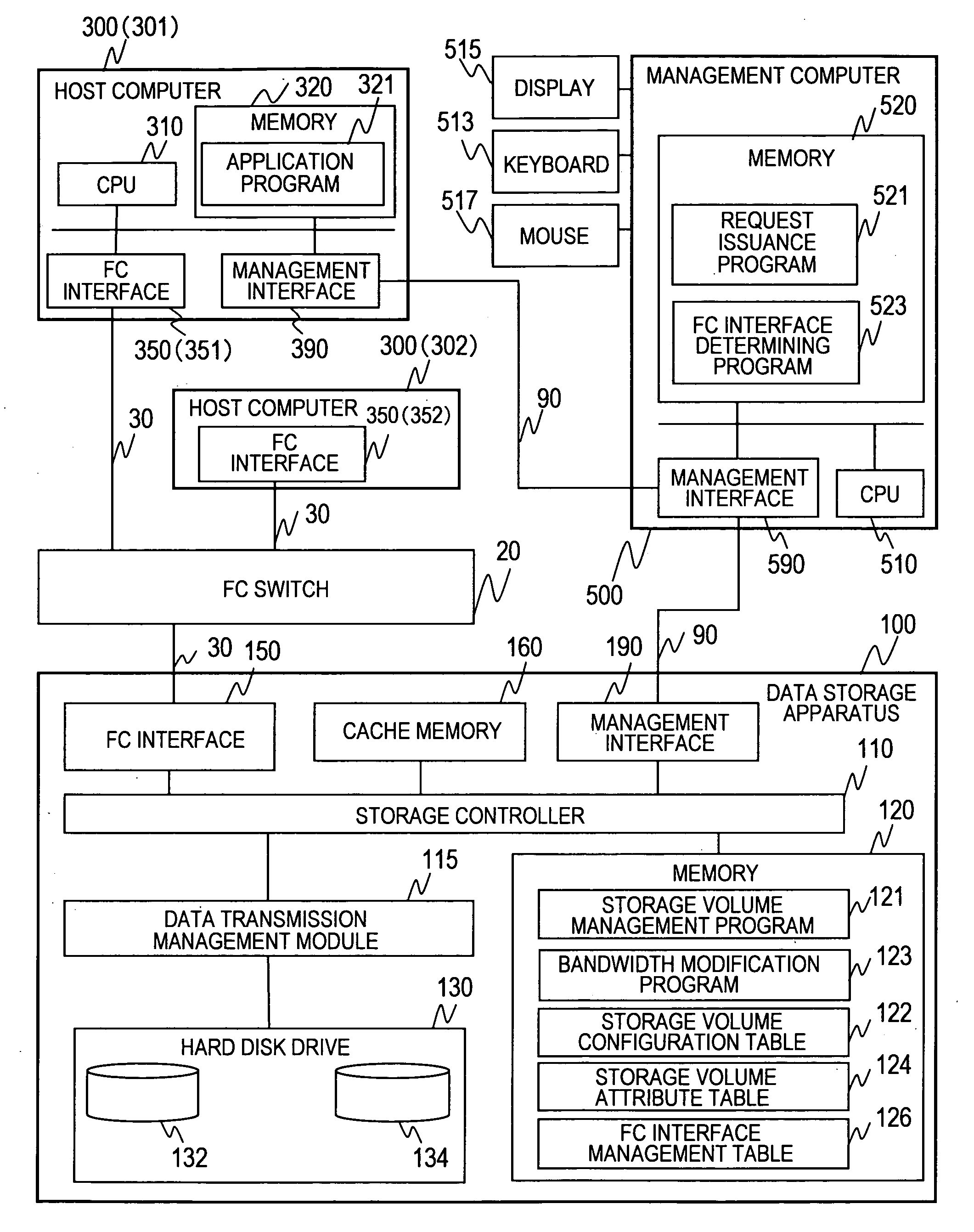
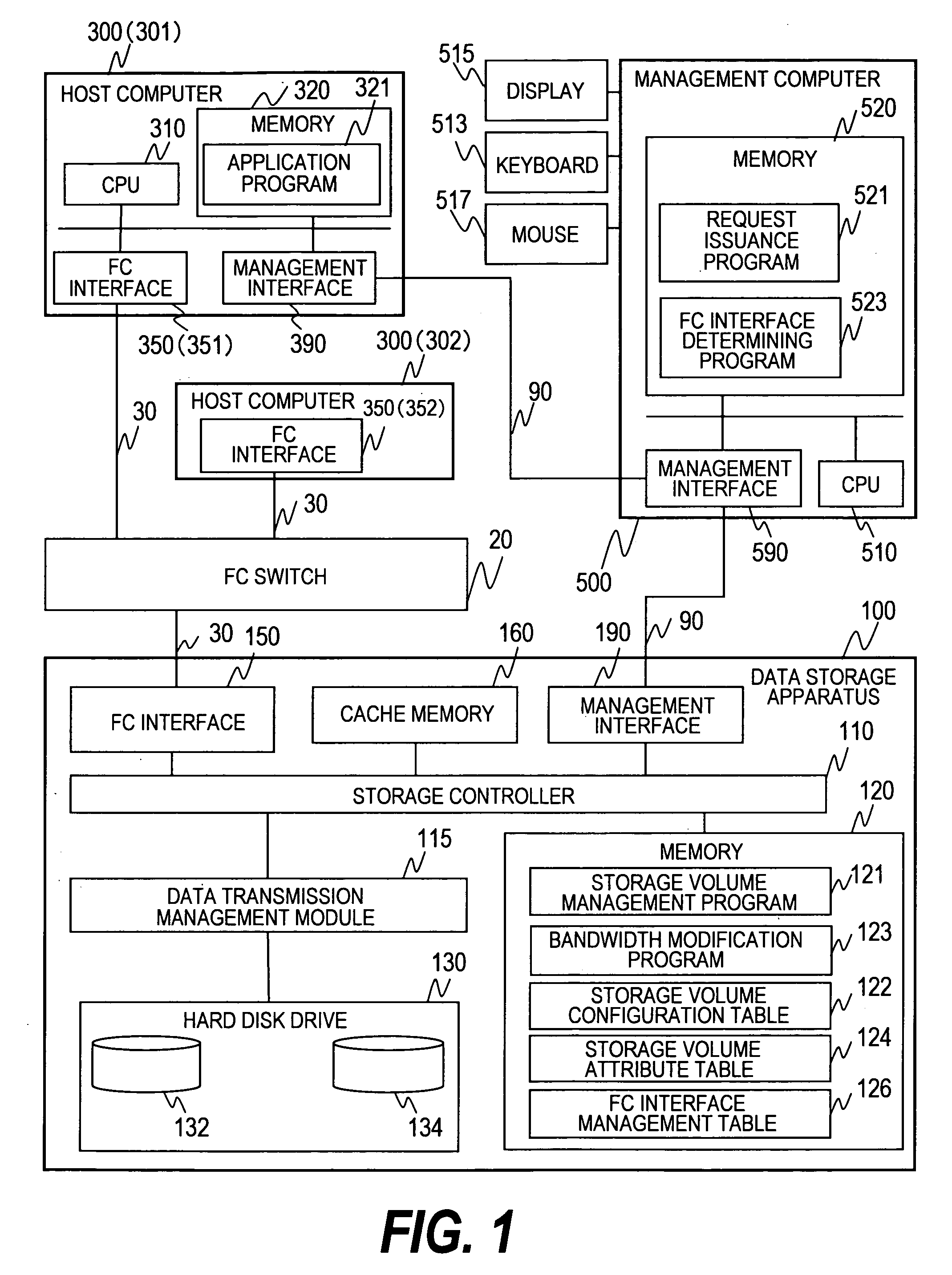
[0055]FIG. 1 is a block diagram showing a configuration of a computer system according to a first embodiment of this invention.

[0056]In the computer system shown in FIG. 1, two host computers 300 are connected to a data storage apparatus 100 via a fibre channel switch (hereinafter referred to as FC switch) 20. Hereinafter, when the two host computers are differentiated from each other, these computers will be referred to as host computers 301 and 302. The host computer 300 and the FC switch 20, and the FC switch 20 and the data storage apparatus 100 are interconnected via a storage area network (abbreviated to SAN) 30. The computer system includes a management computer 500. The management computer 500 manages allocation / unallocation (release) of a storage volume of the data storage apparatus 100. The management computer 500 and the data storage apparatus 100, and the management computer 500 and the host computer 300 are interconnected via a management network 90. It should be noted ...

second embodiment

[0137]Next, a computer system of a second embodiment of this invention will be described. According to the second embodiment, storage volumes to be accessed by a host computer can be allocated to a plurality of data storage apparatuses. Components similar to those of the first embodiment are denoted by similar reference numerals, and description thereof will be omitted.

[0138]FIG. 19 is a block diagram showing a configuration of the computer system according to the second embodiment.

[0139]A host computer 300 and data storage apparatuses 200 and 400 are interconnected via a network. The data storage apparatuses 200 and 400 are connected to the data storage apparatus 100 via the network.

[0140]Accordingly, a configuration is employed in which the data storage apparatuses 200 and 100 or the data storage apparatuses 400 and 100 are tiered. Storage volumes included in the data storage apparatuses 200 and 400 can be provided to the host computer, or a storage volume of the data storage appa...

third embodiment

[0181]Next, a computer system of a third embodiment of this invention will be described. According to the third embodiment, a bandwidth of a storage volume is modified by moving data stored in a real storage volume to a storage volume mapped with a virtualized data volume. Components similar to those of the first or second embodiment are denoted by similar reference numerals, and description thereof will be omitted.

[0182]FIG. 31 is a block diagram showing a configuration of the computer system according to the third embodiment.

[0183]In the system of FIG. 31, a host computer 300 and a data storage apparatus 600 are interconnected via an FC switch 20. Data storage apparatuses 600 and 100 are interconnected via an FC switch 25. The apparatuses 600 and 100 are tiered. The data storage apparatus 600 can provide its own storage volume to the host computer 300 or a storage volume of the data storage apparatus 100 as a storage volume of the data storage apparatus 600 to the host computer 30...


PUM


Abstract

Provided is a computer system including a plurality of data storage apparatus and manages a bandwidth of a data storage apparatus according to an attribute of a storage volume. A storage system includes an interface for processing access to the storage volume from a host computer, and a control unit for controlling allocation of the storage volume to the host computer. A management computer transmits a request of setting a bandwidth to be accessed by the host computer via the interface in the storage volume to the storage system. The control unit sets the bandwidth corresponding to a ratio of processing access to each storage volume in the storage system based on the request from the management computer, and allocates the storage volume having the bandwidth requested by the host computer set therein to the host computer to be accessed by the host computer to the allocated storage volume.

Description

CLAIM OF PRIORITY[0001]The present application claims priority from Japanese application P2006-151692 filed on May 31, 2006, the content of which is hereby incorporated by reference into this application.BACKGROUND OF THE INVENTION[0002]This invention relates to a bandwidth management method for a data storage apparatus performed based on attributes of storage volumes in a computer system including a plurality of data storage apparatuses.[0003]Information lifecycle management for managing data corresponding to a change in value of the data with a passage of time after the data is generated, has been operated in a computer system for storing the data. According to the information lifecycle management, data is managed to give priority to access to highly important data which has just been created and to suppress access to data becoming less important by a drop in access frequency with a passage of time after creation of the data. To realize the information lifecycle management, a data...

Claims


Application Information

Patent Timeline
Patent Type & Authority Patents(United States)
IPC IPC(8): G06F12/00G06F13/00
CPCG06F3/0613G06F3/0631H04L67/1097G06F3/0665G06F3/067G06F3/0635
Inventor FUJITA, FUMIYAMAMOTO, MASAYUKIMARUYAMA, NAOKOKANEDA, YASUNORI
Owner GOOGLE LLC
Learn More