Dual-polarized microstrip slot antenna and electronic product

A microstrip slot, dual-polarization technology, used in antennas, antenna coupling, antenna grounding devices, etc., can solve the impact of vertical polarization signal polarization synthesis performance, the expansion limit of SAR radar operating frequency band, and it is difficult to take into account at the same time, etc. problem, to achieve the effect of improving polarization synthesis performance, suppressing cross-interference, and reducing cross-polarization level

Pending Publication Date: 2022-07-22
GEER TECH CO LTD
View PDF0 Cites 0 Cited by
  • Summary
  • Abstract
  • Description
  • Claims
  • Application Information

AI Technical Summary

Problems solved by technology

[0004] However, the current dual-polarized microstrip antenna has a relatively narrow bandwidth, usually below 3%; the cross-polarization level is high, and the power gain is usually around -10dBi
Moreover, the expansion of bandwidth and the suppression of cross-polarization interference are a pair of contradictions for dual-polarized microstrip antennas, and it is difficult to balance them at the same time.
Therefore, for some remote sensing positioning products that require wide antenna bandwidth and strict cross-polarization loss, the current dual-polarized microstrip antenna obviously cannot meet the requirements of such products.
Moreover, using it as a SAR antenna in a SAR radar will greatly limit the expansion of the working frequency band of the SAR radar. The polarization synthesis performance of polarized signal and vertically polarized signal has a certain influence

Method used


Image

  • Dual-polarized microstrip slot antenna and electronic product
  • Dual-polarized microstrip slot antenna and electronic product
  • Dual-polarized microstrip slot antenna and electronic product

Examples


Embodiment Construction

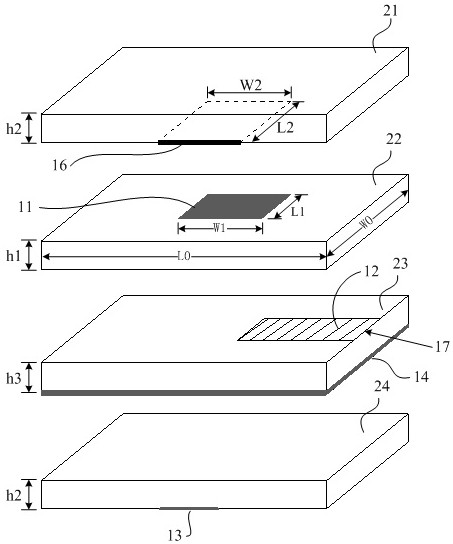
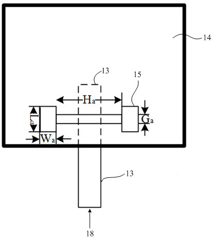
[0029] The specific embodiments of the present invention will be described in further detail below with reference to the accompanying drawings.

[0030] It should be noted that, in the description of the present invention, the terms "upper", "lower", "top", "bottom" and other terms indicating directions or positional relationships are based on the directions or positional relationships shown in the drawings, which are only It is for ease of description, rather than indicating or implying that the device or element must have a particular orientation, be constructed and operate in a particular orientation, and therefore should not be construed as limiting the invention. Furthermore, the terms "first" and "second" are used for descriptive purposes only and should not be construed to indicate or imply their relative importance.

[0031]In addition, it should be noted that, in the description of the present invention, unless otherwise expressly specified and limited, the terms "ins...


PUM


Abstract

The invention discloses a dual-polarized microstrip slot antenna and an electronic product. The dual-polarized microstrip slot antenna comprises a radiation patch, a grounding plate, a first polarized feeder line and a second polarized feeder line, wherein the radiation patch is a main radiator of the antenna, and the size of the radiation patch can be determined according to the center frequency of the antenna; a gap is formed in the grounding plate and is used for gap coupling feeding; the first polarization feeder is located between the radiation patch and the grounding plate and is used for generating electromagnetic coupling with the grounding plate to form excitation and radiating electromagnetic waves to the radiation patch; the second polarization feeder line and the first polarization feeder line are spatially orthogonal and are arranged in a layered manner, the grounding plate is located between the first polarization feeder line and the second polarization feeder line, and the second polarization feeder line radiates electromagnetic waves to the direction of the radiation patch through a gap formed in the grounding plate. According to the invention, a mixed feed technology combining gap feed and proximity coupling feed is adopted, and a structural design of layered arrangement of the polarized feeder lines is matched, so that the bandwidth of the antenna is expanded, and meanwhile, the cross polarization level is reduced.

Description

technical field [0001] The invention belongs to the technical field of antenna devices, and in particular, relates to a dual-polarized microstrip antenna. Background technique [0002] Radar is an electronic detection system that radiates electromagnetic waves and uses the reflection of the electromagnetic waves by objects to find the target and determine the position of the target. Radar can be divided into pulse Doppler radar, synthetic aperture radar, and tracking while scanning radar according to different signal processing methods. Among them, Synthetic Aperture Radar (SAR) is an active earth observation system that can be installed on aircraft, satellites, spacecraft and other flight platforms to observe the earth all day, all weather, and has a certain surface penetration. ability. SAR antenna is a key component of SAR radar, which directly affects the performance of SAR radar. Therefore, rational optimization of SAR antenna design is an important part of SAR radar...

Claims


Application Information

Patent Timeline
Patent Type & Authority Applications(China)
IPC IPC(8): H01Q1/50H01Q1/52H01Q15/24H01Q1/38H01Q1/48H01Q1/22
CPCH01Q1/50H01Q1/52H01Q15/24H01Q1/38H01Q1/48H01Q1/22
Inventor 侯树森
Owner GEER TECH CO LTD
Why Eureka
Try Eureka