Non-drop torsion bar bracket and assembly

a torsion bar and bracket technology, applied in the direction of resilient suspensions, interconnection systems, vehicle springs, etc., can solve the problems of preventing the vehicle from being returned to the stock or original condition, affecting the ride, and affecting the stability of the vehicle, so as to maintain the range of motion

Inactive Publication Date: 2008-09-30
HECKETHORN PRODS
View PDF34 Cites 7 Cited by
  • Summary
  • Abstract
  • Description
  • Claims
  • Application Information

AI Technical Summary

Benefits of technology

[0011]It is therefore a general object of the present invention to provide a lift kit that does not irreversibly damage or alter the vehicle's stock equipment but can be used in connection with a lift kit that does cut or otherwise alter the stock equipment.
[0012]Another object of the present invention is to provide a system that is easy to install.
[0013]Still another object of the present invention is to provide a system that can raise the frame without altering the alignment of the torsion bar and bump stop.
[0015]Another object of the present invention is to provide a system that can maintain the range of motion allowed by the stock-located torsion bar.
[0016]Still another object of the present invention is to provide a system that maintains the stock distance between the torsion bar and the stock control arm in the placement of the torsion bar in contact with the new control arm.

Problems solved by technology

If the control arm did not allow the wheel to move somewhat independently, the vehicle's ride would be very rough indeed.
As a result, present lift kits not only damage the stock equipment but also prevent the vehicle from being returned to stock or original condition.
The fact that exiting lift kits do not allow this certainly affects the future value of the altered vehicles.
However, these systems will not work to raise the frame on modern vehicles such as General Motors Heavy Duty trucks and sport utility vehicles in such a way as to allow the vehicle to be returned to its original equipment later.
This needed system is presently lacking in the art.

Method used


Image

  • Non-drop torsion bar bracket and assembly
  • Non-drop torsion bar bracket and assembly
  • Non-drop torsion bar bracket and assembly

Examples


Embodiment Construction

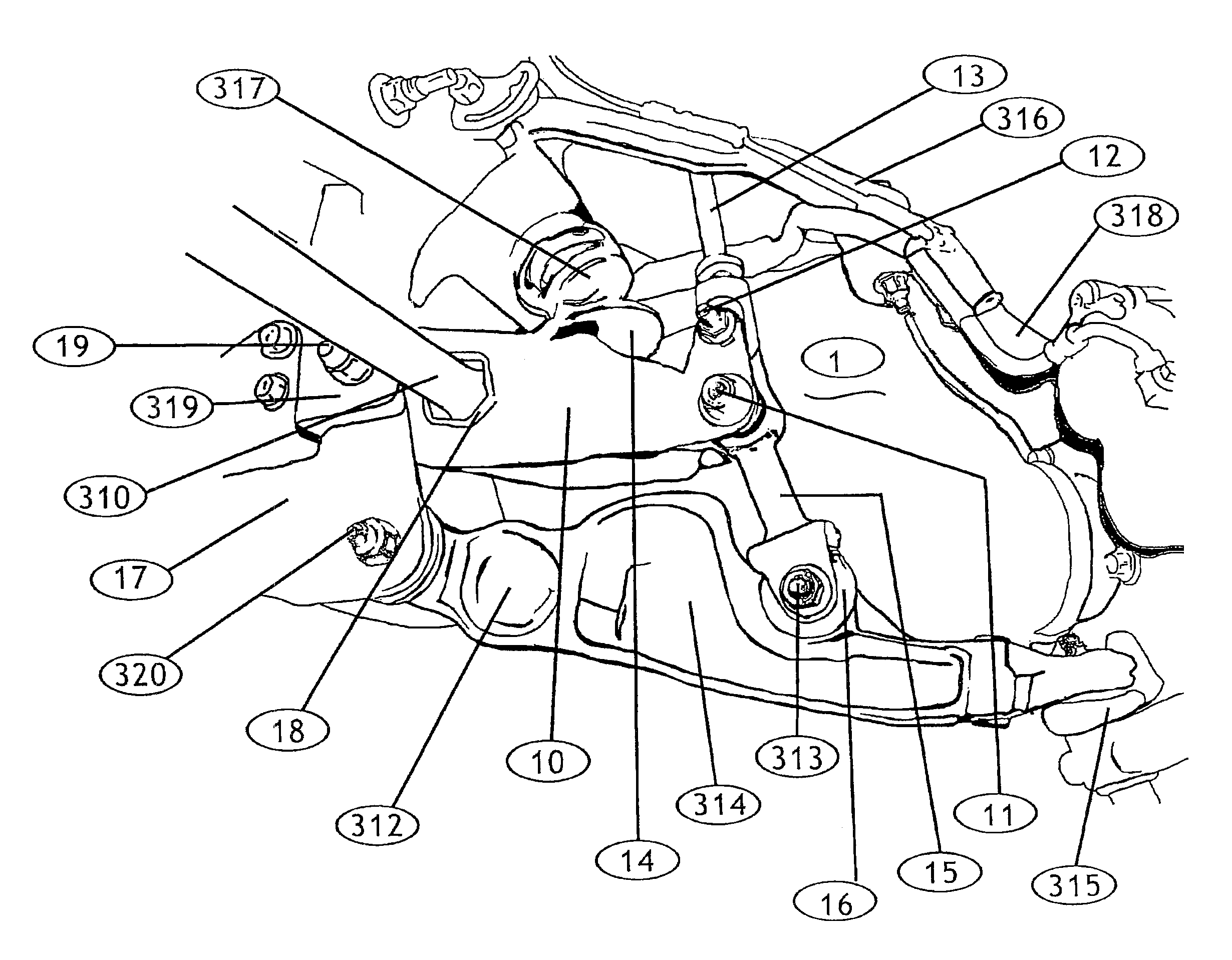
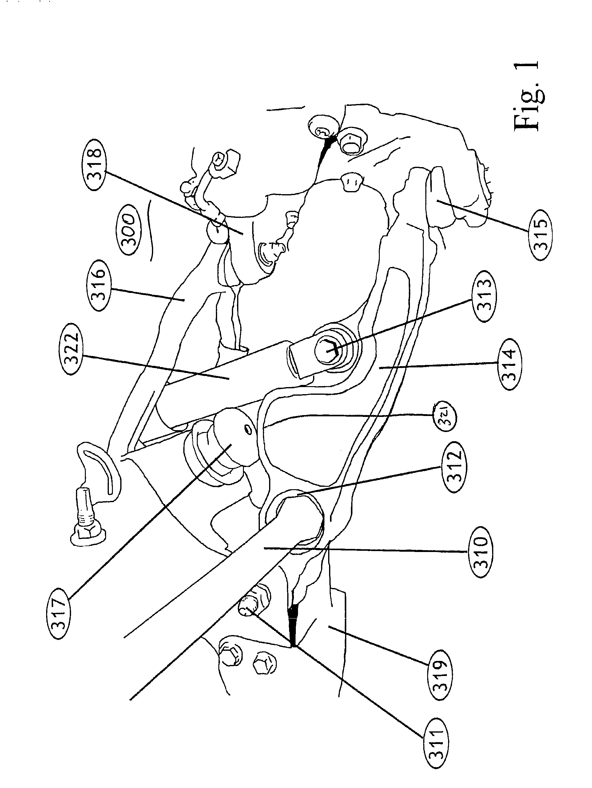
[0027]FIGS. 1 and 2 show a stock or existing suspension assembly 300 for a motor vehicle. Stock torsion bar 310 is joined on one end to the frame torsion bar cross member 328 that includes a torsion bar adjuster assembly 324 and is received at the other end by the torsion bar socket 312 in the stock lower control arm 314. The stock lower control arm 314 is pivotally connected to the stock frame 319 by stock lower control arm pivot point 311. The stock lower control arm 314 also has stock lower shock mount 313 that pivotally attaches to a stock shock absorber 322. The stock lower control arm 314 is joined to stock lower ball joint 315 providing connection from the stock frame 319 to the ball joint 315 and therefore to the wheel assembly (not shown). The stock lower control arm 314 is also provided with a stock bump stop pad 321 that contacts stock bump stop 317. The stock assembly 300 is also provided with an upper control arm 316 joined to stock steering knuckle 318.
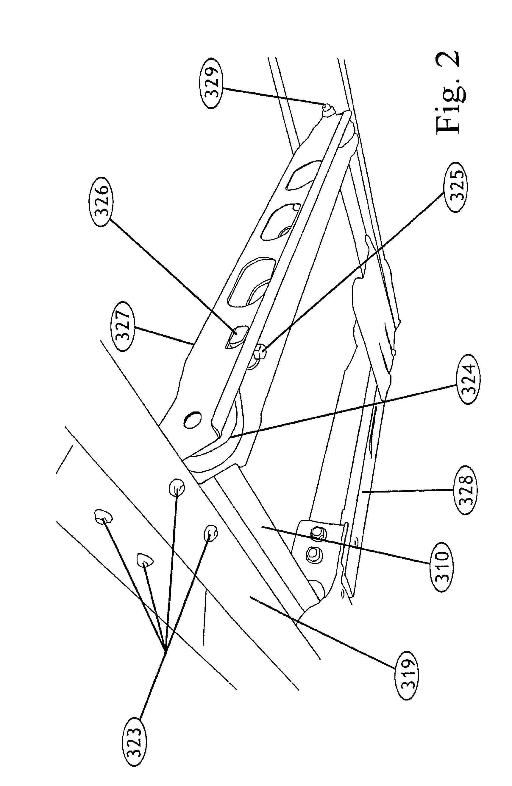
[0028]FIG. 3 sho...


PUM


Abstract

The present invention discloses a vehicle lift kit that allows a vehicle to be lifted or raised from the ground without moving the stock torsion bar bracket and assembly. The present lift kit has a drop bracket having a front pivot point, a rear pivot point, and a torsion bar socket for receiving a torsion bar of the vehicle. The lift kit also provides a link attached to the front pivot point of the drop bracket and a stock control arm and a bracket attachable to the rear pivot point of the drop bracket and the stock control arm. The drop bracket may have a bump stop pad. The link attaches to a shock mount of the stock control arm. The bracket is attaches to a pivot point of the stock control arm. The link has a body joining an upper hole and a lower hole.

Description

[0001]A portion of the disclosure of this patent document contains material that is subject to copyright protection. The copyright owner has no objection to the facsimile reproduction by anyone of the patent document or the patent disclosure, as it appears in the U.S. Patent and Trademark Office patent file or records, but otherwise reserves all copyright rights whatsoever.[0002]All patents and publications described or disclosed herein are hereby incorporated by reference in their entirety.BACKGROUND OF THE INVENTION[0003]The present invention relates generally to a system relating to the suspension system for a motorized vehicle. More specifically, the invention relates to a system that raises the frame of a motorized vehicle farther from the ground to provide greater ground clearance without requiring that the existing or original equipment suspension system be damaged or cut. More specifically the present invention relates to a non-drop torsion control bracket that can be attach...

Claims


Application Information

Patent Timeline
Patent Type & Authority Patents(United States)
IPC IPC(8): B60G3/14B60G21/055
CPCB60G11/181B60G11/20B60G2202/134B60G2204/122B60G2500/30B60G2204/422B60G2204/61B60G2206/01B60G2204/1226
Inventor TURNER, MARK
Owner HECKETHORN PRODS
Why Eureka
Try Eureka