
Droplet discharging device and method of detecting discharge abnormality thereof

a technology of droplet discharge and abnormal discharge, which is applied in the direction of printing, other printing apparatuses, etc., can solve the problems of inability to discharge droplets, image quality deterioration, etc., and achieve the effect of simple structure, accurate detection of residual vibration of vibrating plate, and enhanced precision in the detection of discharge abnormalities of droplets

Active Publication Date: 2008-09-30
SEIKO EPSON CORP
View PDF12 Cites 25 Cited by
  • Summary
  • Abstract
  • Description
  • Claims
  • Application Information

AI Technical Summary

Benefits of technology

This approach enhances the precision and reliability of detecting discharge abnormalities in a simple structure, allowing for accurate identification of clogging causes without the need for optical sensors, thereby improving image quality by preventing dot dropouts.

Problems solved by technology

An inkjet head (a printing head) of the inkjet printer is provided with a large number of nozzles, and there are some cases in which the ink drops cannot be discharged because some of the nozzles are clogged due to an increase in the viscosity of an ink, the entrainment of bubbles or the adherence of dust or paper dust.
If the nozzles are clogged, dot dropouts are produced within an image so that image quality is deteriorated.

Method used


Image

  • Droplet discharging device and method of detecting discharge abnormality thereof
  • Droplet discharging device and method of detecting discharge abnormality thereof
  • Droplet discharging device and method of detecting discharge abnormality thereof

Examples


first embodiment

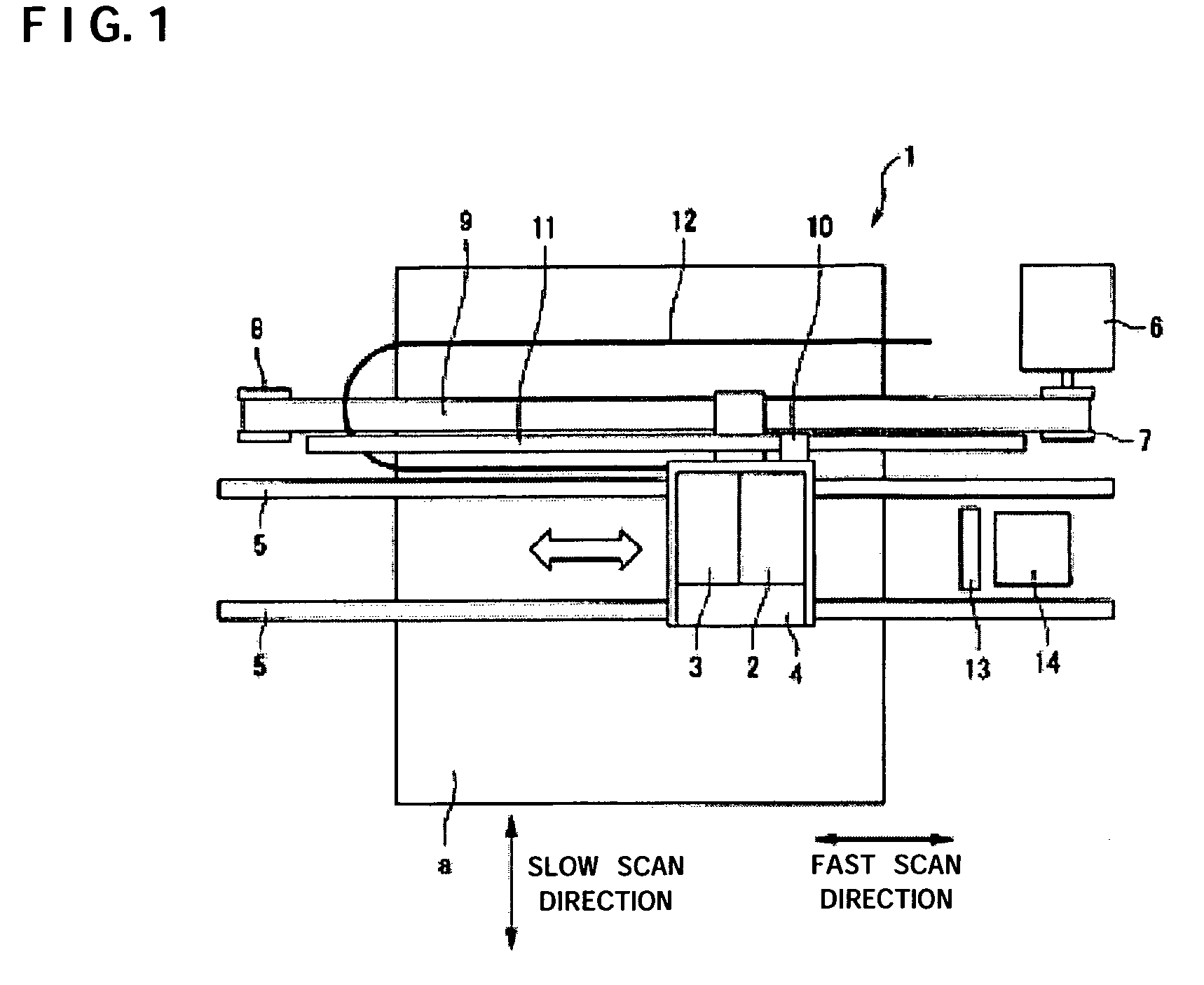
[0044]FIG. 1 is a plan view showing the schematic structure of an inkjet printer 1 to be one of droplet discharging devices according to a first embodiment of the invention.

[0045]The inkjet printer 1 comprises a carriage 4 mounting a head unit 2 and an ink cartridge 3 thereon as shown in FIG. 1, and the carriage 4 can be guided by a pair of carriage shafts 5 and can be thus moved in a fast scan direction. Moreover, a part of the carriage 4 is fixed to a toothed belt 9, and the toothed belt 9 is laid between a driving pulley 7 and a driven pulley 8 which are fixed to the rotating shaft of a motor 6.

[0046]Furthermore, an encoder 10 is attached to the carriage 4 and a linear scale 11 is provided in the direction of movement of the carriage 4. Consequently, the position of the head unit 2 on the carriage 4 is detected by the encoder 10.

[0047]In FIG. 1, 12 denotes a cable for electrically connecting the head unit 2 and a system controller. 13 denotes a wiper for cleaning the surface of a...

second embodiment

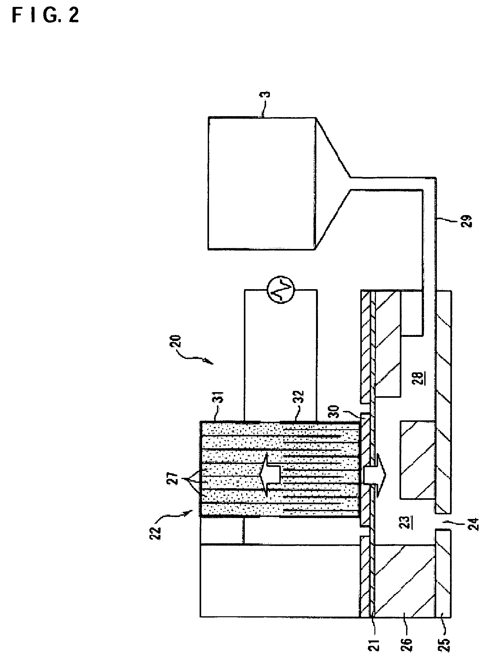
[0122]Referring to FIGS. 2 and 13, next, description will be given to a second embodiment of the invention in which the detection of a residual vibration is carried out when the discharge abnormality of each nozzle of each inkjet head 20 (the dot dropouts of the nozzle) is to be detected based on the detection principle of the residual vibration described above.

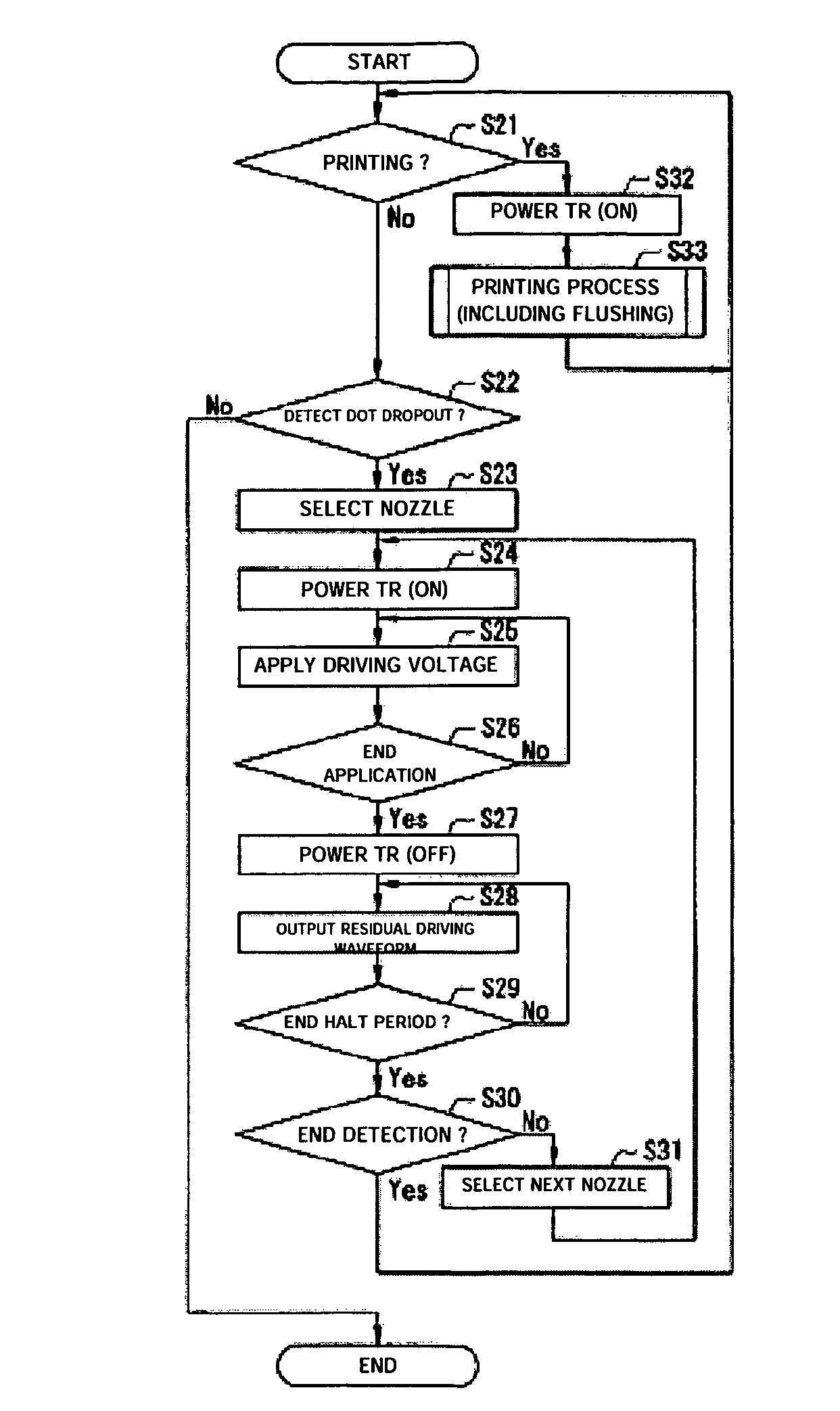
[0123]In the second embodiment, as shown in FIG. 13, there are provided at least a plurality of piezoelectric actuators 22a to 22e, a driving circuit 41 to be a driving unit, a nozzle selecting portion 42 to be a nozzle selecting unit, a residual vibration detecting circuit 43 to be a residual vibration detecting unit, a transistor 47 to be a switch unit, and a control circuit 48 to be a switch control unit.

[0124]More specifically, a structure according to the second embodiment has common components to the structure according to the first embodiment shown in FIG. 8, and is different in that the transistor 44 and the switch 45...


PUM


Abstract

A droplet discharging device is provided which does not require a special sensor (an optical sensor) and can enhance the precision of detecting a discharge abnormality of ink droplets. When printing is to be carried out, a transistor having a large current capacitance is turned on, a driving signal is applied from a driving circuit to piezoelectric actuators, and ink droplets are discharged by corresponding nozzles. Upon detecting a discharge abnormality of the nozzles, one of the piezoelectric actuators corresponding to the nozzles is selected, the transistor is turned off and a switch is turned on. A driving voltage is then applied from the driving circuit to the piezoelectric actuator thus selected in this state. When the application of the driving voltage ends, the switch is turned off. Consequently, a residual vibration detecting circuit detects the electromotive voltage of the piezoelectric actuator by the residual vibration of a vibrating plate.

Description

RELATED APPLICATIONS[0001]This application claims priority to Japanese Patent Application Nos. 2004-092356 filed Mar. 26, 2004 and 2004-159366 filed May 28, 2004 which are hereby expressly incorporated by reference herein in their entirety.BACKGROUND[0002]1. Technical Field[0003]The present invention relates to a droplet discharging device such as an inkjet printer and a method of detecting a discharge abnormality thereof.[0004]2. Related Art[0005]An inkjet printer to be one of droplet discharging devices discharges ink drops (droplets) from a plurality of nozzles, thereby forming an image on a predetermined paper. An inkjet head (a printing head) of the inkjet printer is provided with a large number of nozzles, and there are some cases in which the ink drops cannot be discharged because some of the nozzles are clogged due to an increase in the viscosity of an ink, the entrainment of bubbles or the adherence of dust or paper dust. If the nozzles are clogged, dot dropouts are produce...

Claims


Application Information

Patent Timeline
Patent Type & Authority Patents(United States)
IPC IPC(8): B41J29/393B41J2/15B41J2/01B41J2/045B41J2/055B41J2/165
CPCB41J2/0451B41J2/16579B41J2/04581B41J2002/14354
Inventor SHINKAWA, OSAMU
Owner SEIKO EPSON CORP
Learn More