Retrofit digital mammography detector

a digital and detector technology, applied in the field of medical imaging systems, can solve the problems of chemical or thermal processing, delay in obtaining diagnostic images, and difficulty in providing radiographic images outside of immediate medical facilities

Active Publication Date: 2008-09-30
CARESTREAM HEALTH INC
View PDF11 Cites 43 Cited by
  • Summary
  • Abstract
  • Description
  • Claims
  • Application Information

AI Technical Summary

Benefits of technology

[0027]It is an advantage of the present invention that it provides a digital radiography retrofit device that uses existing automatic exposure control systems.
that it provides a digital radiography retrofit device that uses existing automatic exposure control systems.

Problems solved by technology

Problems with conventional film based systems include delay in obtaining a diagnostic image, the requirement for chemical or thermal processing, and difficulty in providing the radiographic image outside of the immediate medical facility.
One aspect of conducting radiographic imaging is the importance of controlling the amount of X-ray exposure that the patient and the detector receive since excessive exposure to this ionizing radiation can be harmful to the patient and would create undesirable density levels on film.
However, among other problems, the CR systems still result in a delay in obtaining a diagnostic image due to the necessity of removing the CR cassette from its position within the imaging apparatus and scanning the exposed CR plate.
Today's solid-state, ionizing radiation-based image detectors (hereafter DR detector) used in projection digital radiography are relatively large and expensive.
There are a number of design constraints with these devices.
Cost remains a significant problem.
As a result, DR systems are very expensive and the current market is small given the high cost of investment.
Present DR detector based systems are not compatible with film-based systems, thus do not provide a digital imaging solution for the large installed base of X-ray imaging systems that presently support film or CR cassettes.
), discloses a filmless digital X-ray system that is designed to be compatible with standard X-ray cassette housing external dimensions, but does not provide compatibility with existing mammography AEC systems.
), disclose small area mammography spot imaging detectors that are used for diagnostic procedures such as needle biopsies and are compatible with film cassette holders but do not provide full field imaging capability or compatibility with AEC systems.
U.S. Pat. No. 6,800,870 (Sayag), discloses a CR screen and reading system that is compatible with film cassette based X-ray exposure systems but requires readout of a storage phosphor plate after exposure, thus delaying image availability.
U.S. Pat. No. 6,734,441 (Wendlandt), discloses features of a CR cassette design that is compatible with AEC systems but still requires readout of a storage phosphor plate after exposure, thus delaying image availability.
However, proposed solutions for DR retrofit apparatus have not addressed the particularly challenging requirements of full-field mammography imaging.
Providing the required chest wall access distance is yet a further challenge.

Method used


Image

  • Retrofit digital mammography detector
  • Retrofit digital mammography detector
  • Retrofit digital mammography detector

Examples


Embodiment Construction

[0041]The following is a detailed description of the preferred embodiments of the invention, reference being made to the drawings in which the same reference numerals identify the same elements of structure in each of the several figures.

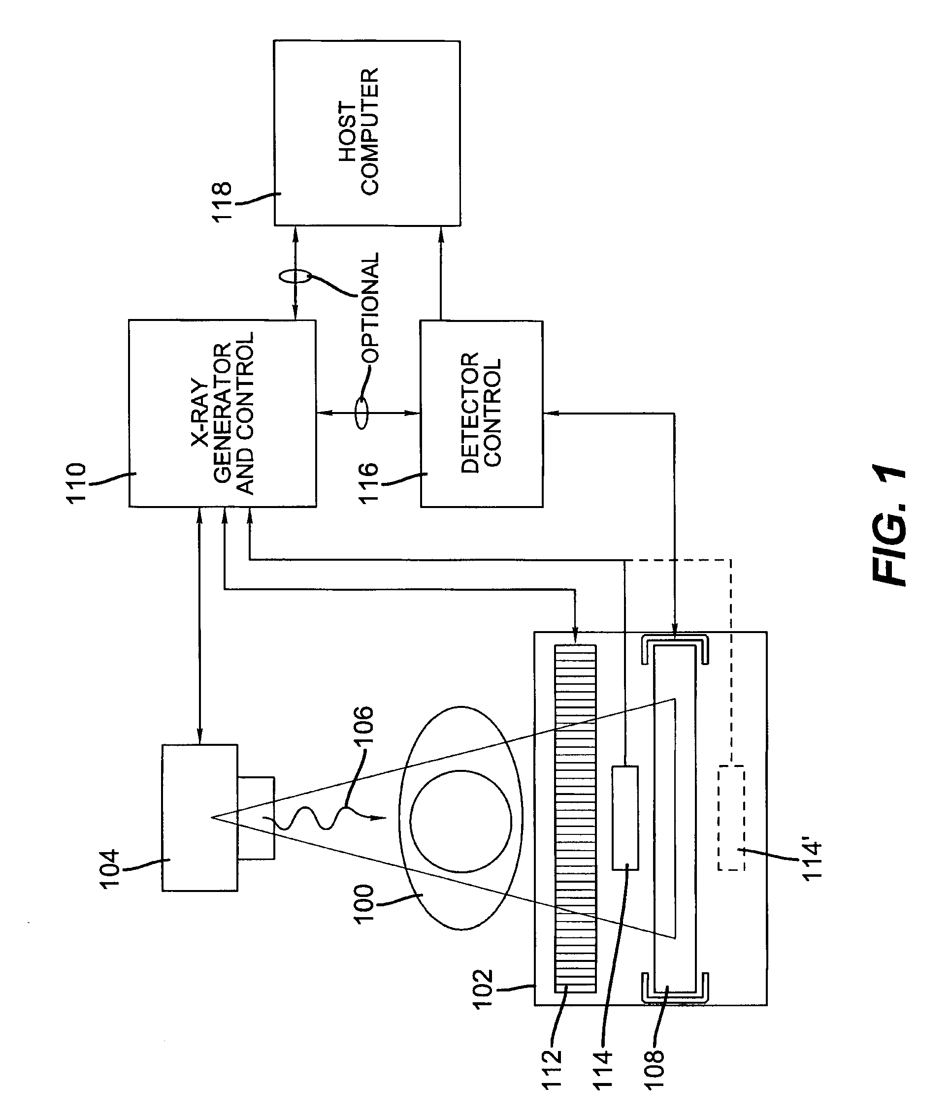
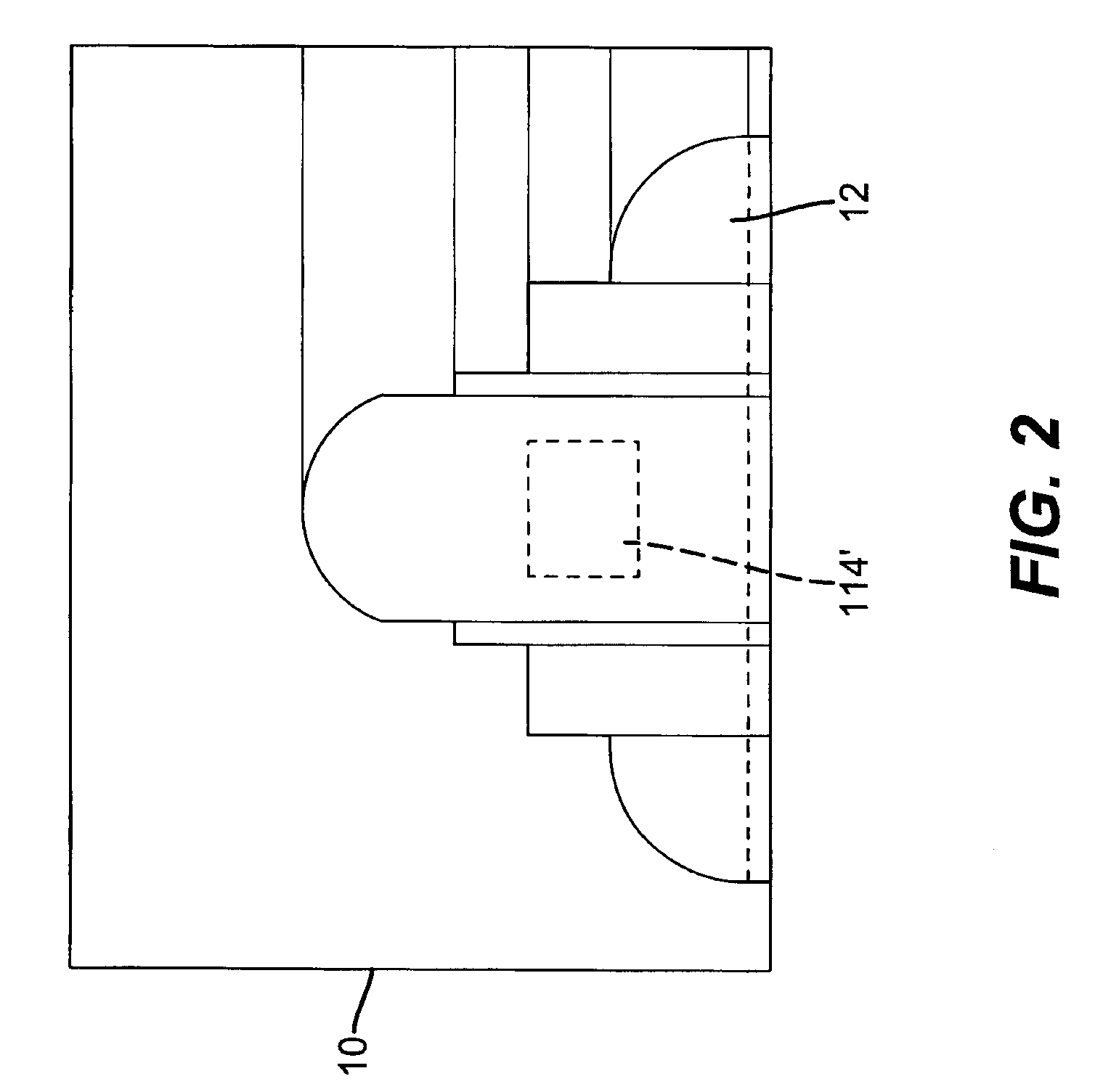
[0042]Referring now to FIG. 1, there is shown a typical projection X-ray apparatus used in an X-ray examination room. As shown, a patient 100 is positioned on a support 102. An X-ray source 104 projects X-rays 106 through a body part of patient 100 to form a radiographic image of the corresponding anatomy, which is detected by a digital detector housed in a radiography cassette 108 mounted in support 102. X-ray source 104 is activated and controlled by an X-ray generator and control 110. Support (Bucky) 102 can also house an antiscatter grid 112. An auto exposure control (AEC) sensor 114 can be positioned in the path of X-rays 106, prior to radiography cassette 108. Alternately, as is generally practiced for mammography, an auto exposure control (AE...


PUM


Abstract

A digital radiography (20) detector has a first housing (18) having substantially the form factor of a film cassette and having a chest wall edge (C). The first housing (18) has an X-ray converter (70) with a detection array (26), each detector generating a signal according to an amount of radiation received. Readout electronics (74) are coupled with switching elements in the detection array for obtaining the signals therefrom. The readout electronics (74) include elements formed from crystalline silicon and are distributed toward outer edges of the first housing (18) and away from the chest wall edge (C). X-ray shielding selectively protects the readout electronics (74) and is located beneath a portion of the detection array. A second housing (40), electrically connected to the first housing (18) has a power source for the detector, readout and control electronics for obtaining signals provided from the detection array (26).

Description

CROSS REFERENCE TO RELATED APPLICATIONS[0001]Reference is made to commonly-assigned copending U.S. patent application Ser. No. 11 / 441,584, filed May 26, 2006, entitled COMPACT AND DURABLE ENCASEMENT FOR A DIGITAL RADIOGRAPHY DETECTOR, by Jadrich et al., and to U.S. patent application Ser. No. 11 / 409,883, filed Apr. 24, 2006, entitled WIRELESS X-RAY DETECTOR FOR A DIGITAL RADIOGRAPHY SYSTEM WITH REMOTE EVENT DETECTION, by Dhurjaty et al., the disclosures of which are incorporated herein.FIELD OF THE INVENTION[0002]This invention relates in general to medical imaging systems that use digital radiography detectors, and more particularly to a digital radiography detector that can be retrofit into an existing film-based mammography exposure system.BACKGROUND OF THE INVENTION[0003]Traditional film-screen radiography has been used as a medical imaging diagnostic system for many years. X-rays are projected through a patient's body part to irradiate a cassette containing a scintillator scree...

Claims


Application Information

Patent Timeline
Patent Type & Authority Patents(United States)
IPC IPC(8): G01T1/24
CPCA61B6/4233A61B6/502G01T1/244G01T1/2928A61B6/563
Inventor WOJCIK, TIMOTHY J.BYNG, JEFFREY W.JADRICH, BRADLEY S.SHAFER, MARK E.YIP, KWOK-LEUNG
Owner CARESTREAM HEALTH INC
Why Eureka
Try Eureka