
Positioning assembly

a technology of positioning assembly and assembly plate, which is applied in the direction of mounting board securing, electrical apparatus construction details, casings/cabinets/drawers, etc., can solve the problems of high manufacturing cost, inconvenient practical use, and time-consuming, and achieves the effect of high manufacturing cos

Active Publication Date: 2008-09-30
INVENTEC CORP
View PDF12 Cites 35 Cited by
  • Summary
  • Abstract
  • Description
  • Claims
  • Application Information

AI Technical Summary

Benefits of technology

[0011]Therefore, the efficacy of the present invention is that the circuit board of the electronic device can be quickly and stably mounted on the case by the stopping of the positioning assembly. In other words, because of the special design of the positioning assembly of the present invention, when the circuit board is mounted on the case, as long as the circuit board is pushed along the integrate direction, the circuit board is stably mounted on the case. In this manner, not only it is not necessary to lock or dismount a plurality of screws by screwing, but also it is further possible to mount and dismount the circuit board easily and quickly, thereby reducing the manpower cost required by locking, and fixing the circuit board in the screwless manner at the same time.

Problems solved by technology

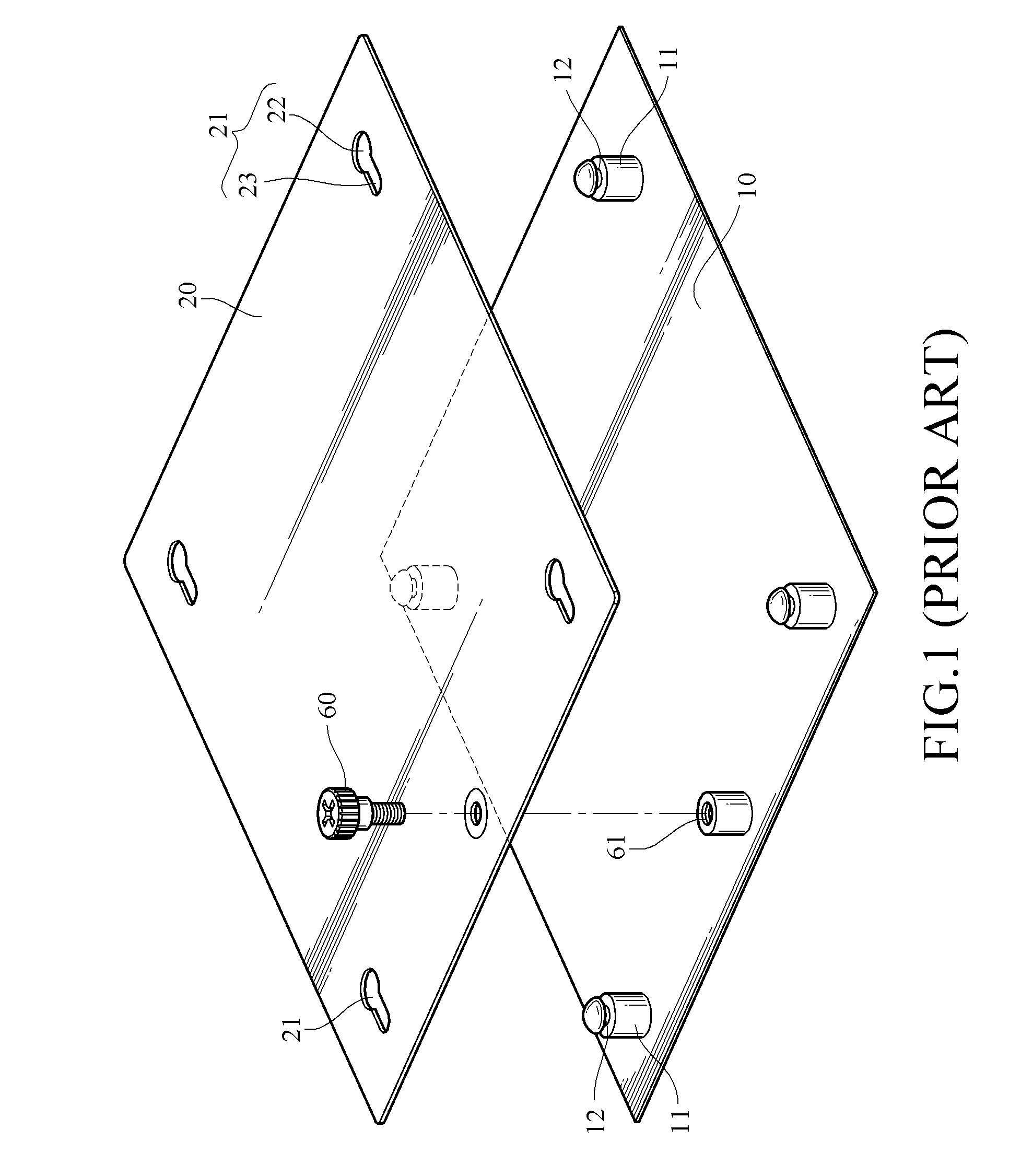
With regard to the conventional method of locking and fixing the mainboard by the conductive bosses, when the mainboard is being mounted and dismounted, a user has to lock and release the bolts one by one with the same actions, which is quite complicated and time-consuming and also inconvenient in practical use.
Furthermore, the present electronic device is required to be light, thin, short, and small, but too many conductive bosses will occupy more area of the mainboard.
The circuit layout on the mainboard cannot be achieved easily, and the volume of the whole electronic device cannot be microminiaturized, either.
However, the method of fixing the motherboard by using the thumb screw is still a locking method by screwing and through this method, the process of mounting and dismounting the mainboard is complicated, not only the cost time is too long, but also the cost of the thumb screw is higher than that of conventional bolt, such that material cost and manpower cost are increased.

Method used


Image

  • Positioning assembly
  • Positioning assembly
  • Positioning assembly

Examples


Embodiment Construction

[0019]The positioning assembly of the present invention is applied in an electronic device which likes a computer device provided with a circuit board to execute actions, such as desktop computers, notebook computers, and severs. In the following detailed description of the present invention, the notebook is used as a preferred embodiment of the present invention. The accompanied drawings are merely provided for reference and illustration and are not intended to limit the present invention.

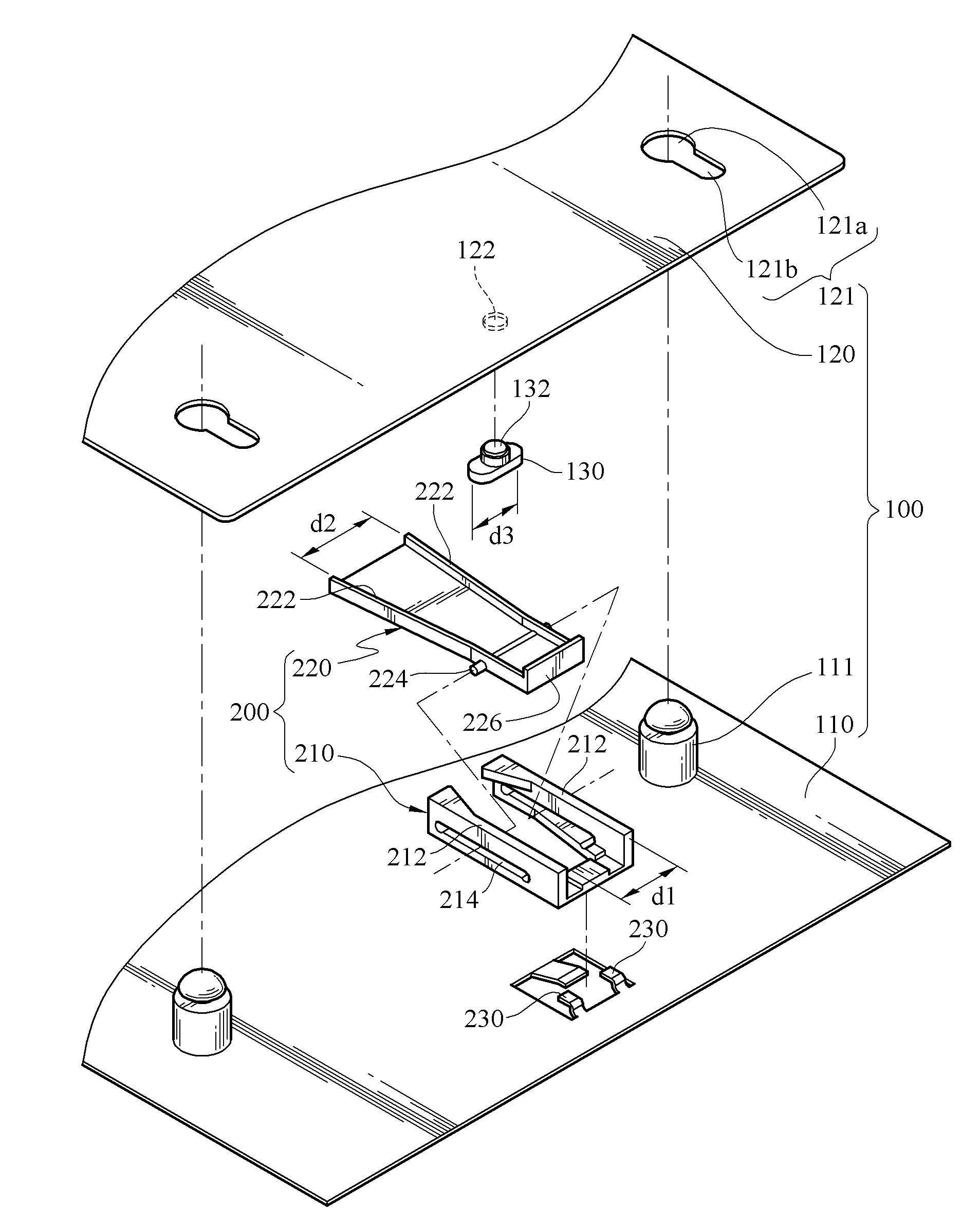
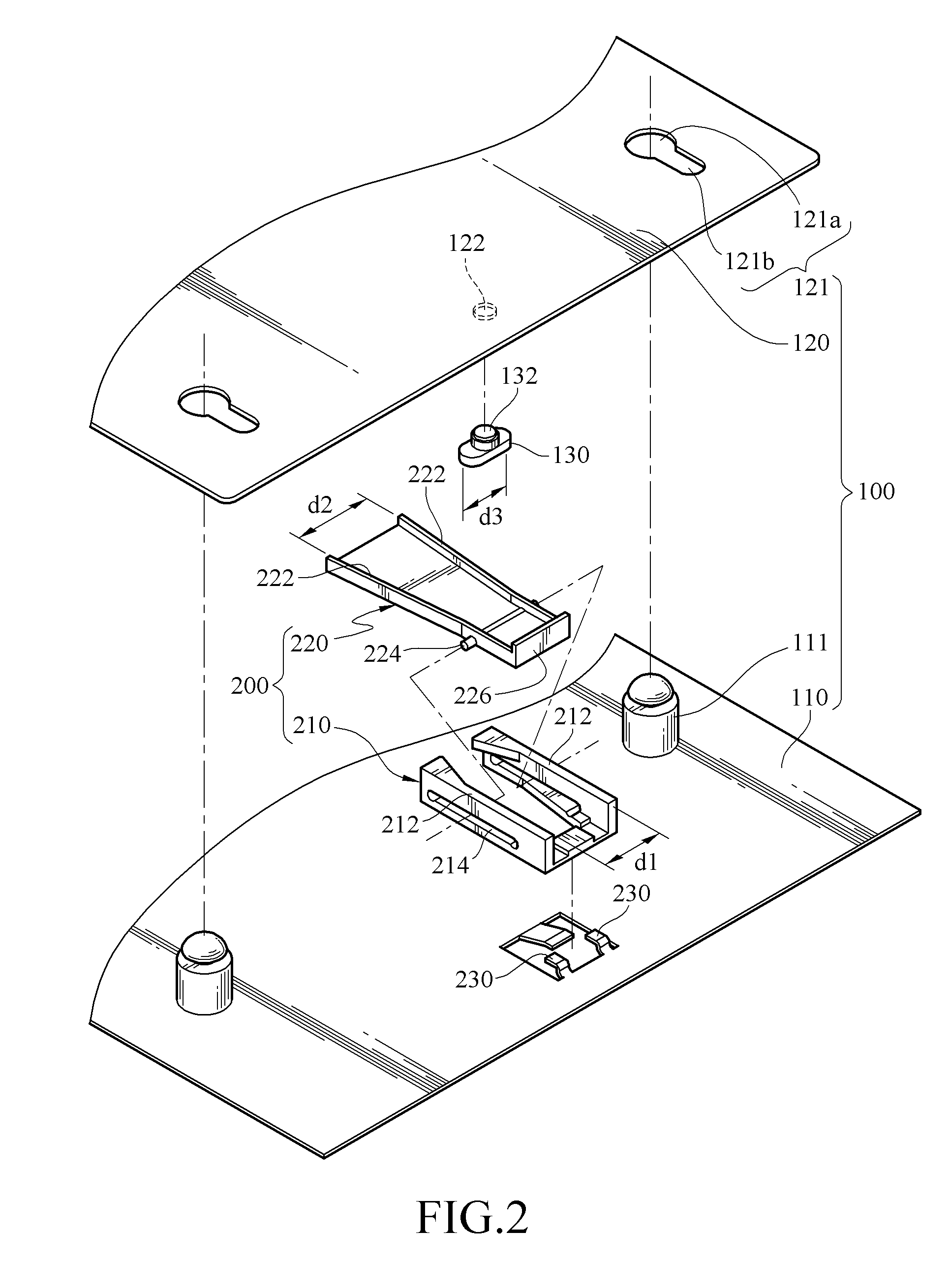
[0020]Referring to FIG. 2, an exploded view of an embodiment of the present invention is shown. A positioning assembly 200 of the present invention is applied to an electronic device 100, and the positioning assembly 200 is used to lean against a movable latching member 130. The electronic device 100 has a case 110 and a circuit board 120, and the latching member 130 is disposed on a side of the circuit board 120 corresponding to the case 110. At least one combination post 111 is disposed on the c...


PUM


Abstract

A positioning assembly is used for positioning a circuit board on a case. The circuit board shifts relative to a case along a integrate direction or a release direction. The positioning assembly includes a fixed member, a movable member, and a latching member. The latching member is disposed on a side surface of the circuit board, and the fixed member is disposed to the case, for the latching member to pass through in a single direction along a integrate direction, such that the latching member is stopped at one end of the fixed member, thereby positioning the circuit board case. The movable member makes the fixed member spread and deform, such that the latching member passes through the fixed member in an opposite direction along a release direction, so that the circuit board may fixed on or detached from the case.

Description

BACKGROUND OF THE INVENTION[0001]1. Field of Invention[0002]The present invention relates to a positioning assembly. More particularly, the present invention relates to a positioning assembly for locking and fixing a circuit board without bolts.[0003]2. Related Art[0004]Currently, with the rapid development of science, technology and information, a computer device has become a quite popular electronic device. In the current market, computer devices, such as desktop computers, notebook computers, or servers, are all provided with a mainboard therein as a kernel member of a compute system, so that computer peripheral hardware, such as a central processing unit (CPU), a memory module, and a PCI card, electrically connected to the mainboard may perform default functions smoothly.[0005]The mainboard is usually fixed as follows. A plurality of conductive bosses is formed on a case of a computer device as fixing means, and a plurality of through holes corresponding to the conductive bosses...

Claims


Application Information

Patent Timeline
IPC IPC(8): H05K7/12H05K7/14
CPCH05K7/142H05K7/1417
Inventor PENG, YING-CHAO
Owner INVENTEC CORP
Learn More