Method and arrangement for performing measurements of the topography of a surface by means of a thermal emission from the surface

a topography and thermal emission technology, applied in the field of performing the topography of the surface, can solve the problems of difficult to see references, marginally invasive, and greatly reduced accuracy, and achieve the effect of reducing the chance of disturbing the measurement results

Inactive Publication Date: 2008-10-07
MAASTRICHT UNIVERSITY
View PDF6 Cites 36 Cited by
  • Summary
  • Abstract
  • Description
  • Claims
  • Application Information

AI Technical Summary

Benefits of technology

[0013]It is an object of the present invention to provide a method and arrangement for performing measurements of the topography of a; surface, such as an eye or corneal surface, which alleviates the problems described above and wherein the surface remains undisturbed, thus reducing the chance of disturbing measuring results by the measuring method itself.
[0015]Projecting the image using, for example, infra-red light provides several benefits. For this colour the eye is not only fully opaque, but the photons that are absorbed by, for instance, a tissue are converted into heat. This heat causes thermal excitation of the matter in the tissue generating radiation comprising wavelengths other than the original wavelength that was projected onto the surface. The light that is not absorbed by the tissue, but may instead be reflected back to the receiving unit (specular reflection, scattering), is still comprised of its original wavelength. This natural process enables filtering of the reflected light from the signal by for example an optical filter or dichroic mirror, leaving only the fraction of light caused by thermal emission to be detected by the detection means. It will be appreciated that this latter fraction comes from the diffusely radiating surface, and provide the diffuse image that can be used in surface mapping methods. This method may in particular be efficient if mid-IR light is used, since the thermally emitted fraction is relatively large for these frequencies. Note further that invention is not limited to the use of mid-IR since other wavelengths may be used for different surfaces than the corneal surface taken here as an example.
[0024]By adjusting the position of the arrangement relative to the position of the surface, one can easily establish the distance for which the surface coincides (on average) with the ‘plane of focus’, by evaluating the pattern formed by said references.
[0027]By focussing on the conjunctiva adjacent to the corneal tissue no visible light load for the patient is present. By using near-IR light the chances of response of the eye to the focussing are further reduced.

Problems solved by technology

The limitations of these methods are that the accuracy is greatly reduced when both convex and concave curvatures are present on the surface or when rays are reflected outside the aperture of the sensor.
A disadvantage of this technique is that it is marginally invasive.
Especially for ophthalmologic purposes this is not desired since the application of fluorescein onto the eye disturbs the tear film and makes it difficult to see references, such as the pupil or the iris, on or beneath the surface of the eye.
Another drawback of this technique is that it does not work on dry surfaces, such as dry eyes.
As mentioned above, the use of a fluorescent layer may not always be desired, especially not in application directed to determining the topography of a corneal surface as the fluorescein disturbs the tear film on said surface.
Disadvantages of the use of UV light, especially in the range for which autofluorescence occurs, is that at these frequencies a surface such as an eye surface may be damaged due to protein denaturation, which may cause actinic conjunctivitis.
A person skilled in the art may appreciate that such a scattering process will be inefficient.

Method used


Image

  • Method and arrangement for performing measurements of the topography of a surface by means of a thermal emission from the surface
  • Method and arrangement for performing measurements of the topography of a surface by means of a thermal emission from the surface
  • Method and arrangement for performing measurements of the topography of a surface by means of a thermal emission from the surface

Examples


Embodiment Construction

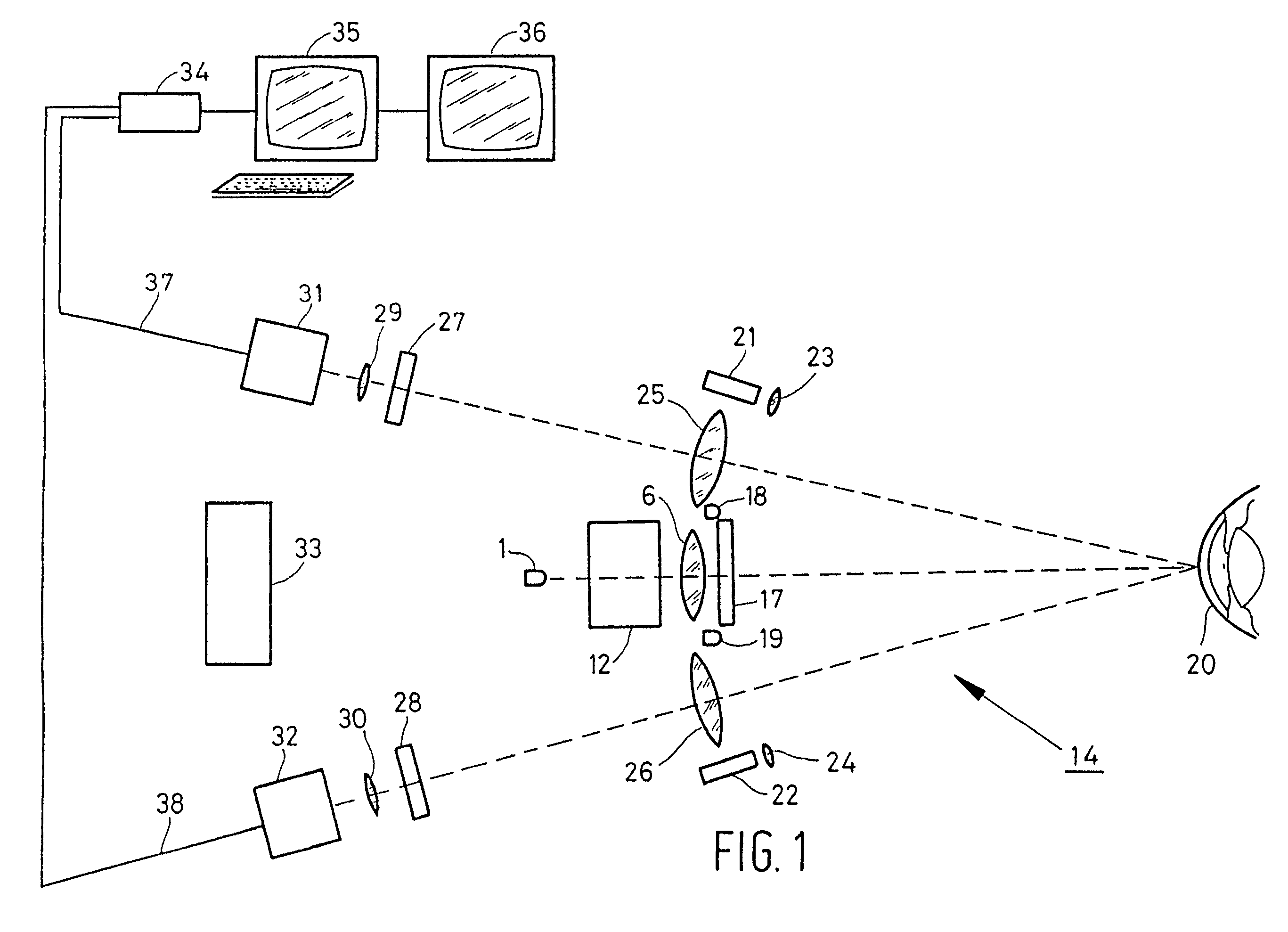
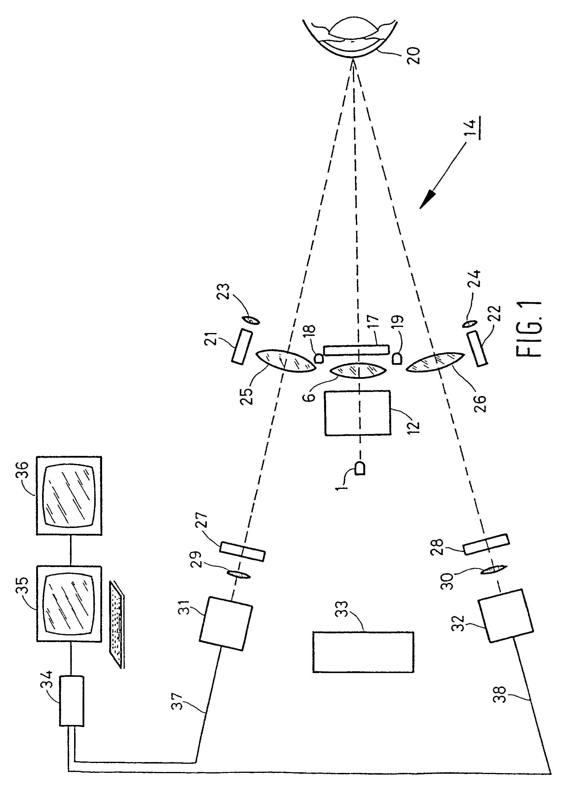
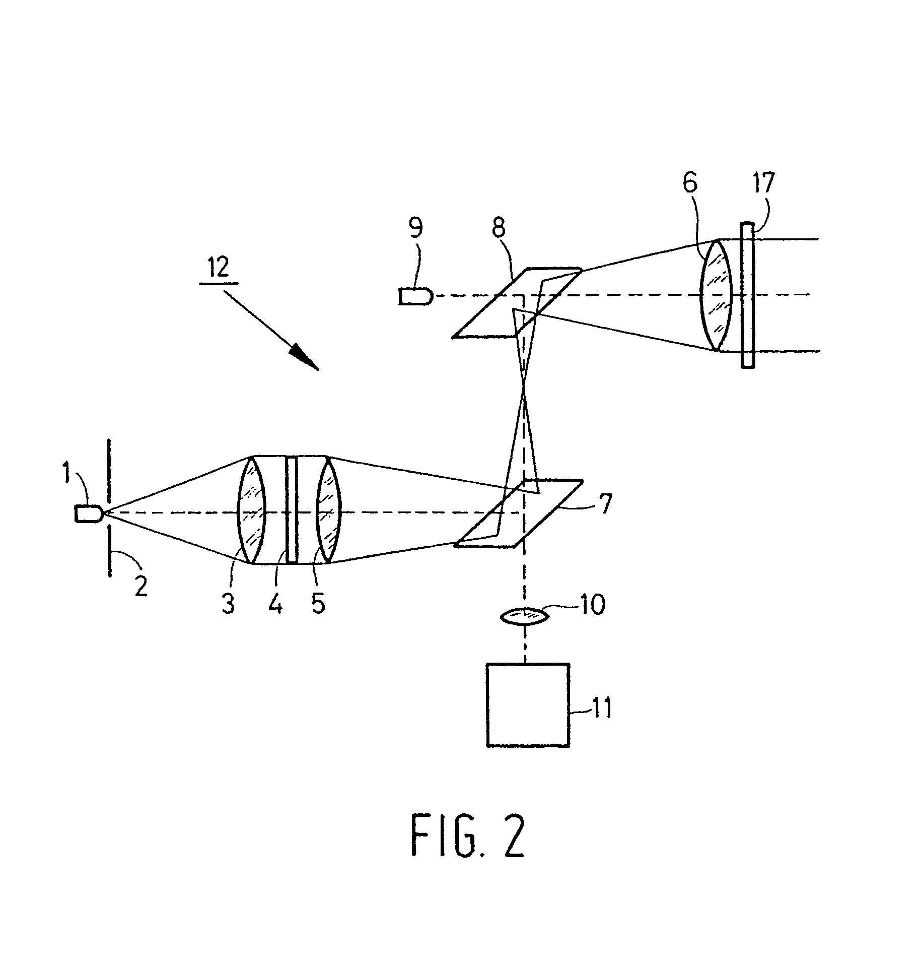
[0043]An arrangement 14 according to the present invention is shown in FIGS. 1 and 2. The arrangement has three main functions: projection of a line pattern on the corneal surface 20, triangulation focussing, and visualisation of references by using ambient light sources 18 and 19. FIG. 1 shows a schematic top view-of the arrangement, and FIG. 2 shows a side view of the projection unit generally indicated as 12.

[0044]Projection on the surface is performed by generating a line pattern projection through light source 1, aperture 2, lens 3, grid 4, telecentric lens 5, (dichroic) mirrors 7 and 8, and telecentric lens 6. The image leaving telecentric lens 6 is projected onto the corneal surface 20. The diffuse image of the grid 4 on the corneal surface 20 is picked up through telecentric lenses 25 and 26, filters 27 and 28, telecentric lenses 29 and 30 and cameras 31 and 32. The signal of cameras 31 and 32 is transmitted via lines 37 and 38 to frame grabber 34 and further processed by PC...


PUM


Abstract

Method and arrangement for performing measurements of the topography of a surface (20), such as topography of an eye surface (20), wherein projecting means (1, 12) for projecting an image onto said surface (20) comprises a projection light source (1), and wherein at least a fraction of light leaving the surface (20) as a result of said projection is received using one or more receiving units (31, 32), such as charged coupled device (CCD) based cameras. The topography of the surface (20) is determined by analysis of said fraction of light leaving the surface (20), due to thermal emission and the image projected onto the surface (20) is projected with light comprising a colour for which the surface (20) is opaque, such as infrared light.

Description

FIELD OF THE INVENTION[0001]The present invention relates to a method for performing measurements of a topography of a surface, such as the topography of an eye surface, wherein an image is projected onto said surface from at least one projection light source using projection means, wherein at least a fraction of light leaving the surface as a result of said projection is received using one or more receiving units, such as charged coupled device (CCD) based cameras, wherein measurement of said topography relates to surface mapping of said surface, wherein said topography of the surface is determined by analysis of said fraction of light leaving the surface, and wherein said fraction of light leaving the surface is comprised of light radiated by the surface due to thermal emission.[0002]The invention further relates to an arrangement for performing measurements of the topography of a surface, such as topography of an eye surface, wherein measurement of said topography relates to surf...

Claims


Application Information

Patent Timeline
Patent Type & Authority Patents(United States)
IPC IPC(8): A61B3/10A61B3/107A61B5/00G01B11/25G01B21/08
CPCA61B3/107G01B11/25A61B5/015
Inventor JONGSMA, FRANCISCUS HERMANUS MARIADE BRABANDER, JOHNY
Owner MAASTRICHT UNIVERSITY
Why Eureka
Try Eureka