Catalytic filter for removing soot particulates from diesel engine exhaust and method of preparing the same

a technology of catalytic filter and diesel engine, which is applied in the direction of catalyst activation/preparation, metal/metal-oxide/metal-hydroxide catalyst, and air quality improvement, etc., which can solve the problems of increasing visual discomfort, affecting human health, and affecting the degree of air pollution

Active Publication Date: 2008-10-07
SK ENERGY CO LTD (KR)
View PDF17 Cites 40 Cited by
  • Summary
  • Abstract
  • Description
  • Claims
  • Application Information

AI Technical Summary

Benefits of technology

[0009]Leading to the present invention, the intensive and thorough research on catalytic filters for removal of soot particulates from diesel engine exhaust, carried out by the present inventors aiming to avoid the problems encountered in the related art, resulted in that a colloidal solution of a platinum group metal (PGM) salt and a metal salt impregnated on a catalyst support is used, instead of conventional aqueous metal salt solutions, thus obtaining a monolithic oxidation catalyst upstream of the catalytic filter, which effectively oxidize volatile organic fractions, and a catalyzed wall-flow filter downstream thereof serving to low temperature combustion of soot particulates collected on the filter, thereby removing soot particulates in exhaust gas.

Problems solved by technology

Especially, soot particulates, caused by incomplete combustion of diesel fuel, increase visual discomfort and the degree of air pollution that causes offensive odors, and as well, can damage human health.
Therefore, emission control standards for soot particulates in diesel engine exhaust have been further strengthened, but practically applicable technologies satisfying the current emission control standards have not been presently commercially developed.
As for the method of reducing emissions of the soot particulates, desirable results cannot be obtained by the improvement of engine technology alone for some vehicles.
Meanwhile, the use of fuel additives is not cost-effective and may cause secondary pollution by emission thereof into the atmosphere.
However, use of the post-treatment device suffers from excessive increase of back- pressure due to the accumulation of the trapped soots when the trapped soots are not continuously regenerated, resulting in worsening engine performance.
However, the above process is disadvantageous in that excessive thermal shock applied to the filter medium leads to the damage of filter medium, while negating economic benefits due to the use of complicated control units.
Additionally, the regeneration process of the filter medium by adding an organic metal additive to diesel fuel is disadvantageous in that the added metal component is deposited in the engine, and fine metallic additive particles not trapped in the filter medium is discharged to the atmosphere, thus causing secondary pollution.

Method used


Image

  • Catalytic filter for removing soot particulates from diesel engine exhaust and method of preparing the same
  • Catalytic filter for removing soot particulates from diesel engine exhaust and method of preparing the same
  • Catalytic filter for removing soot particulates from diesel engine exhaust and method of preparing the same

Examples


example 1

[0053](1) Preparation of Colloidal Metal Salt Solution

[0054]Platinic Colloidal Solution

[0055]In a 2 L flask, 252 g of polyvinylpyrrolidone (average molecular weight: 10,000, Aldrich Chemical) was dissolved in 1 L of deionized water to make a uniform solution, which was then added with 30.4 g of chloroplatinic acid and 1 L of methanol with vigorous stirring. The solution was refluxed at 80° C. for 6 hours, and filtered to obtain 2,070 g of a dark brown platinic colloidal solution containing 0.62 wt % of platinum.

[0056]Preparation of Aqueous Metal Salt Solution

[0057]15.4 g of ammonium molybdate, 40 g of magnesium nitrate, and 10 g of potassium hydroxide were added to 250 mL of deionized water with vigorous stirring, to prepare aqueous solutions of molybdenum, magnesium, and potassium.

[0058]Preparation of Colloidal Solution Mixture

[0059]The above platinic colloidal solution was mixed with the aqueous magnesium solution at a weight ratio of 1:1, to make a colloidal metal salt solution f...

example 2

[0062]A catalytic wall-flow filter for removal of soot from diesel engine exhaust was prepared in the same manner as in Example 1, with the exception that flow-through ceramic monolith having a diameter of 10.5 inch, a length of 3 inch and a cell density of 400 cpsi, and wall-flow ceramic filter (Corning Inc.) having a diameter of 10.5 inch, a length of 12 inch and a cell density of 200 cpsi, were used as substrates for the oxidation catalyst and the catalyzed wall-flow filter.

example 3

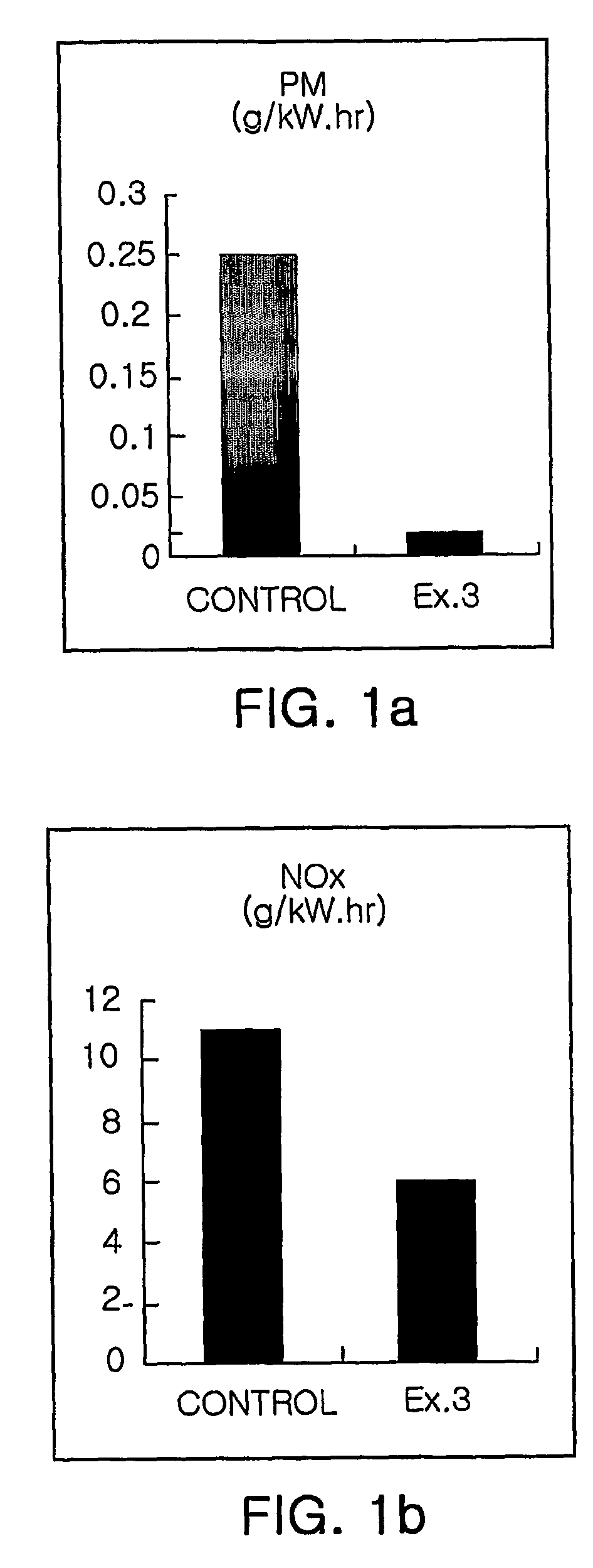
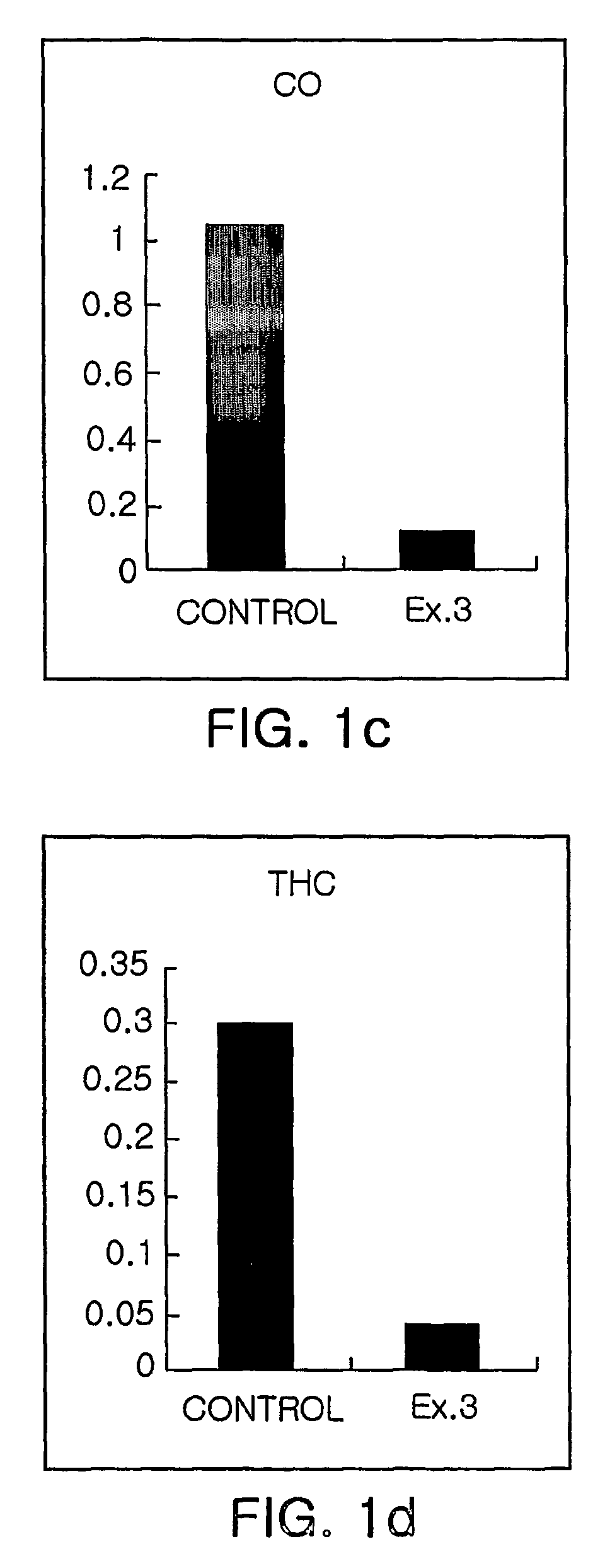
[0063]The catalytic filter prepared in Example 2 mounted to an exhaust pipe of Hyundai Aerocity Bus 540 having an exhaust air volume of 11,149 cc, and subjected to field test in D-13 mode. Subsequently, the reduction of soot particulates in exhaust gas was measured. The results are depicted in FIGS. 1a to 1d.

[0064]As is shown in FIGS. 1a to 1d, the catalytic filter of the present invention reduced 92% or more of soot particulates (PM), 85% of CO and HC, and 19% of NOx.


PUM

PropertyMeasurementUnit
weight ratioaaaaaaaaaa
diameteraaaaaaaaaa

Abstract

Disclosed is a catalytic filter for removing soot particulates from diesel engine exhaust, which is comprised of monolithic oxidation catalyst upstream of the catalytic filter, which effectively oxidize gaseous pollutants and volatile organic fractions, and a catalyzed wall-flow filter downstream serving to low temperature combustion of soot particulates collected on the filter. Also, the preparation method of the catalytic filter is provided, including the colloidal mixture solution of platinum group metal salts and other metal salts with a water-soluble polymer and a reducing agent, which is then impregnated on a catalyst support, followed by calcining at high temperatures. In the present invention, use of the catalytic filter provides effective means of abating diesel exhaust pollutant emissions, that is, particulate matter (PM) and gaseous pollutants (HC, CO, NOx).

Description

TECHNICAL FIELD[0001]The present invention relates to catalytic wall-flow filters for removal of soot particulates from diesel engine exhaust, and preparation methods thereof. More specifically, the present invention relates to a catalytic filter system, capable of continuously burning soot trapped on the filter, thereby regenerating the filter while reducing harmful exhaust gases of carbon monoxide (CO), nitrogen oxides (NOx) and unburned hydrocarbons (HC) therein, as well, and a method of preparing the catalytic filter.BACKGROUND ART[0002]Generally, particulate matters in diesel engine exhaust are composed of carbonaceous soot particulates with average diameter of 0.3 μm, comprising soots, sulfates and heavy hydrocarbons, which are derived from lubricating oil and unburned fuel. Especially, soot particulates, caused by incomplete combustion of diesel fuel, increase visual discomfort and the degree of air pollution that causes offensive odors, and as well, can damage human health. ...

Claims


Application Information

Patent Timeline
Patent Type & Authority Patents(United States)
IPC IPC(8): B01D46/00B01D50/00B01D53/34F01N3/022B01D39/00B01D53/94B01J23/56B01J23/652B01J35/00B01J35/04B01J37/02B01J37/03B05D1/12B32B27/02F01N3/035
CPCB01D53/944B01D53/945B01J23/56B01J23/6525B01J35/0006B01J35/04B01J37/0211B01J37/038F01N3/035B01D2255/102B01D2258/012B01J35/0013Y10S55/05Y10S55/30Y10S55/10Y02T10/22Y02A50/20Y02T10/12B01D39/00
Inventor KIM, YONG-WOOMIN, JOON-SEOKKIM, SUNG-HYOANLEE, CHANG-QMIN, WHA-SIK
Owner SK ENERGY CO LTD (KR)
Why Eureka
Try Eureka