
Method for Controlling Nox Emissions in the Fccu

a technology of nox and nox, which is applied in the direction of physical/chemical process catalysts, metal/metal-oxide/metal-hydroxide catalysts, and separation processes, etc. it can solve the problems of nox present, not enough oxygen to convert/burn all reduced species regardless, and not enough to all. , to achieve the effect of reducing nox present, reducing nox, and oxidizing reduced nitrogen species

Inactive Publication Date: 2008-09-04
WR GRACE & CO CONN
View PDF60 Cites 13 Cited by
  • Summary
  • Abstract
  • Description
  • Claims
  • Application Information

AI Technical Summary

Benefits of technology

[0024]Another advantage of the invention is to provide FCC processes which are effective to oxidize reduced nitrogen species and to reduce NOx present in a FCCU regeneration zone operating in a heterogeneous mode of combustion without increasing the production of either NOx or reduced nitrogen species under any combustion mode in the FCCU regenerator.
[0025]It is also an advantage of the present invention to provide FCC processes for the reduction of NOx emissions from a FCCU regeneration zone operating in a heterogeneous combustion mode due to multistage or multiple regeneration vessels in the regeneration zone.
[0026]Yet another advantage of this invention is to provide improved FCC processes for the reduction of NOx emitted in the off gas released from a FCCU regenerator operating under heterogeneous combustion conditions.
[0027]These and other aspects of the present invention are described in further detail below.

Problems solved by technology

NOx, or oxides of nitrogen, in flue gas streams exiting from FCC regenerators is a pervasive problem.
Thus all FCCUs processing nitrogen-containing feeds can have a NOx emissions problem due to catalyst regeneration.
On the other hand, when the amount of air added to the FCCU regenerator is insufficient to fully oxidize the coke on the cracking catalyst to CO2 and H2O, some of the coke remains on the catalyst, while a significant portion of the coke carbon burned is oxidized only to CO.
However, should any oxygen be present in the regenerator off gas, it is typically not enough to convert all of the CO in the gas stream to CO2 according to the chemical stoichiometry of
That is, there is not enough oxygen to convert / burn all reduced species regardless if some oxygen is actually still present.
Due to poor mixing, the pollutants formed in each area (e.g., CO, SOx, reduced nitrogen and sulfur species in the reducing areas, and SOx and NOx in the oxidizing areas) may not have sufficient time to react with gases from other areas and produce a flue gas having the expected composition for the nominal mode of operation of the regenerator.
Additional complexity is introduced by the different air grid designs employed for air distribution, and the various catalyst / flue gas separation system designs used.
In extreme cases, when L / D is too low for the air superficial velocity employed, channeling of gases through the bed may occur.
A large L / D value can also result in increased catalyst traffic through the cyclones, increase back pressure and impact the distribution of both spent catalyst and air throughout the regenerator vessel.
However, even in this mode of operation, NOx emissions persist and any reduced nitrogen species left is converted to NOx in a downstream CO boiler and is emitted as NOx along with any unreacted NOx escaping the regenerator.
Clearly, the use of additives under such conditions presents a particularly difficult challenge to the FCCU operator for several reasons.
First, since additive compositions are typically circulated throughout the entire FCCU, the additives will be subjected to various combustion conditions.
Secondly, each combustion mode requires a different chemistry to reduce NOx emissions released from a FCCU regeneration zone operating under heterogeneous combustion conditions during a FCC process.
Thirdly, an additive suited for reducing emissions under one combustion regime may be ineffective under another combustion regime and may even promote an increase of NOx emissions under the other combustion regime.

Method used


Image

  • Method for Controlling Nox Emissions in the Fccu
  • Method for Controlling Nox Emissions in the Fccu
  • Method for Controlling Nox Emissions in the Fccu

Examples


example 1

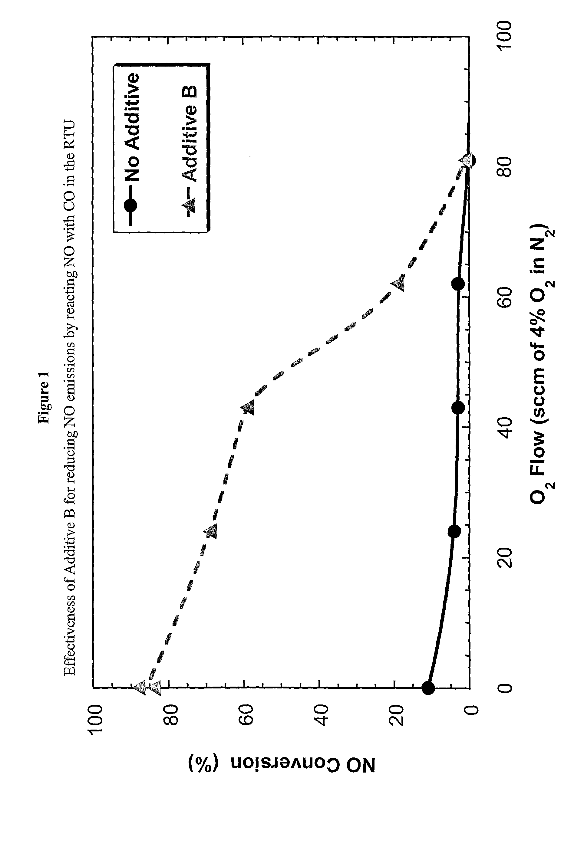
[0096]Ferrierite zeolite was exchanged with copper ions using a solid-state exchange procedure as follows: Copper chloride (120 grams, dry basis) was ground into a fine powder and then blended with 1800 g of ferrierite powder. The blend was calcined for 4 hours at 325° C. The calcined blend was slurried with 9000 g of water maintained at 80° C., stirred for 10 minutes and then filtered. The filtercake was washed three times with 80° C. water, dried at 100° C. for 10 hours and then calcined at 593° C. for 1.5 hours. The finished product contained 2.3% Cu.

[0097]A composition comprising 65% of the Cu-exchanged ferrierite, 15% clay and 20% alumina sol was prepared by forming an aqueous slurry containing 1522 g of aluminum chlorohydrol solution (23% solids), 1138 g (dry basis) of the Cu-exchanged ferrierite and additional water in an amount sufficient to make a slurry containing about 40% solids. The slurry was milled in a Drais mill to an average particle size of less than 2.5 μm and th...

example 2

[0098]The activity of Additive A for reducing NO emissions from an FCC unit was assessed by using the Davison Circulating Riser (DCR). The DCR has been described in G. W. Young, G. D. Weatherbee, and S. W. Davey, “Simulating commercial FCCU yields with the Davison Circulating Riser (DCR) pilot plant unit,” National Petroleum Refiners Association (NPRA) Paper AM88-52; and in G. W. Young, “Realistic Assessment of FCC Catalyst Performance in the Laboratory,” in Fluid Catalytic Cracking: Science and Technology, J. S. Magee and M. M. Mitchell, Jr. Eds., Studies in Surface Science and Catalysis, Volume 76, p. 257, Elsevier Science Publishers B.V., Amsterdam 1993, ISBN 0-444-89037-8, which description is herein incorporated by reference.

[0099]In this experiment, the DCR was operated at “full burn” conditions, that is with 1% excess O2 in the regenerator, and with the regenerator operating at 705° C. The DCR was initially charged with a blend of 1895.25 g of an equilibrium cracking catalyst...

example 3

[0101]A microspheroidal particulate support material was prepared as follows: A slurry was prepared from an aqueous slurry having 20% solids of a peptizable alumina (Versal 700 alumina powder obtained from La Roche Industries Inc., 99% Al2O3, 30% moisture). The alumina slurry was prepared using 31.6 lbs of the alumina. To the alumina slurry 3.87 lbs of an aqueous sodium hydroxide solution (50% NaOH) was added. Then, 10.4 lbs of cerium carbonate crystals (obtained from Rhone Poulenc, Inc., 96% CeO2, 4% La2O3, 50% moisture) was added to the slurry. The slurry was diluted with a sufficient amount of water to bring the solids concentration at 12%. Finally, 3.38 lbs of exchanged silica sol of Nalco 1140 (obtained from Nalco Chemicals Co.) was added to the slurry. The mixture was agitated to assure good mixing and then milled in a stirred media mill to reduce agglomerates to substantially less than 10 microns. The milled slurry was fed to a 10 ft diameter Bowen Engineering spray drier to ...


PUM

PropertyMeasurementUnit
mean particle sizeaaaaaaaaaa
pore sizeaaaaaaaaaa
molar ratioaaaaaaaaaa

Abstract

Processes for the reduction of NOx emissions from a regeneration zone during a fluid catalytic cracking of a hydrocarbon feedstock into lower molecular weight components are disclosed. The processes comprise contacting during a fluid catalytic cracking (FCC) process where NOx emissions are released from a regeneration zone of a fluid catalytic cracking unit (FCCU) operating in a heterogeneous combustion mode under FCC conditions, a hydrocarbon feedstock with a circulating inventory of a FCC cracking catalyst and a NOx reduction composition. The NOx reduction composition comprises: (1) at least one reduced nitrogen species component having the ability to reduce the content of reduced nitrogen species to molecular nitrogen under reducing or partial burn FCC conditions and (2) at least one NOx reduction component having the ability to convert NOx to molecular nitrogen under oxidizing or full burn FCC conditions. The reduced nitrogen species and the NOx reduction components do not significantly increase the content of reduced nitrogen species or NOx under any mode of combustion during a FCC process.

Description

FIELD OF THE INVENTION[0001]The present invention relates to NOx reduction compositions and the method of use thereof to reduce NOx emissions in refinery processes, and specifically in fluid catalytic cracking (FCC) processes. In particular, the present invention relates to NOx reduction compositions and processes for reducing NOx emissions released from a FCC unit (FCCU) regeneration zone operating under a heterogeneous combustion mode during a FCC process.BACKGROUND OF THE INVENTION[0002]An increased concern about air pollution from industrial emissions of noxious oxides of nitrogen, sulfur and carbon have led governmental authorities to place limits on allowable emissions of one or more of such pollutants. Clearly, the trend is in the direction of increasingly stringent restrictions.[0003]NOx, or oxides of nitrogen, in flue gas streams exiting from FCC regenerators is a pervasive problem. FCCUs process hydrocarbon feeds containing nitrogen compounds, a portion of which is contain...

Claims


Application Information

Patent Timeline
Patent Type & Authority Applications(United States)
IPC IPC(8): B01D53/56
CPCB01J21/005C10G2300/80B01J23/63B01J23/83B01J23/894B01J29/061B01J29/072B01J29/084B01J29/68B01J29/74B01J29/76B01J29/80B01J35/0006B01J35/023B01J35/1019B01J37/0045B01J2229/42C10G11/182C10G2300/405B01J23/10B01J35/19B01J35/40B01J35/615B01J29/90B01J23/90B01J8/18B01D53/56
Inventor YALURIS, GEORGERUDESILL, JOHN ALLENKRISHNAMOORTHY, MEENAKSHI SUNDARAMDOUGAN, TIMOTHY J.
Owner WR GRACE & CO CONN
Learn More