Sulphur-Tolerant Anode For Solid Oxide Fuel Cell

a fuel cell and solid oxide technology, applied in cell components, transportation hydrogen technology, electrochemical generators, etc., can solve the problems of reducing the power production of the psofc until, degrading the performance of the anode of the psofc beyond acceptable limits, and achieving high current density, efficient oxidation of hydrogen, and long service li

Inactive Publication Date: 2008-06-12
OHIO UNIV
View PDF6 Cites 13 Cited by
  • Summary
  • Abstract
  • Description
  • Claims
  • Application Information

AI Technical Summary

Benefits of technology

[0023]The invention is a multiple-layer, preferably a two-layer, anode that produces a high current density, and sustains power generation for long periods of time (>10,000 hrs) using gasified coal containing H2S as a fuel. The anode uses multiple anode layers specifically formulated to produce sulfur tolerance and efficiently oxidize hydrogen with a resistance comparable to current PSOFC anodes.
[0024]The preferred embodiment has two reaction zones in the anode that are formed in layers. The first reaction zone, located in the outer layer, allows for a slower diffusion of H2S into the anode than for molecular hydrogen, and has a higher oxidation rate of H2S during its diffusion than for molecular hydrogen. This layer is made of a material that is highly active toward the oxidation of H2S and has a morphology (e.g., pore size) within a preferred range. The second reaction zone, located in the inner layer of the PSOFC, allows rapid and efficient oxidation of hydrogen with a low resistance that will allow for a high current density with low overpotential.
[0026]The invention thus comprises the addition of a “protective” layer of sulfur-tolerant material on a Ni / GDC layer. The combination of these two layers prevents the H2S from attacking the inner anode layer formulated for H2 oxidation by causing H2S to slowly diffuse, and by oxidizing the H2S during that diffusion. The sulfur tolerant layer of the PSOFC acts as a selective membrane that allows more rapid diffusion of H2 through its structure than H2S to allow the H2S to be electrochemically oxidized by the protective layer during the slow diffusion.

Problems solved by technology

However, fuel cells used for automotive transport, such as Polymer Electrolyte Membrane (PEM; also called Proton Exchange Membrane) cells, only use H2, because CO is not compatible with PEM cells.
One substantial problem limiting the use of coal with PSOFCs is the sulfur in coal.
H2S degrades the performance of the anode of the PSOFC beyond acceptable limits.
For example, as little as 0.5 ppm of H2S can cause potential losses that drastically reduce power production by the PSOFC until failure.
Although the H2S concentration in coal syngas may be reduced to approximately 200-300 ppm with the addition of solid adsorbents into the gasification column, this range will still cause damage to the PSOFC.
Since the sulfur content of oxygen-blown gasified coal may only be reduced to a range of 200 to 300 ppm H2S with the use of solid adsorbents, Ni / YSZ cermet anodes cannot be used for the PSOFCs in a distributed power generation source using gasified coal as the fuel source.
Higher temperatures require the use of ceramic interconnects, which are a magnitude higher in cost than their metallic counterparts.
Although this performance is much better than Ni / YSZ cermet anodes, which resulted in an instantaneous increase of 200 percent in the PSOFC resistance with a fuel gas containing only 5 ppm H2S, the overall degradation in the performance of the PSOFC is still too high to be used in a distributed power generation system using gasified coal.
Although these materials have shown good resistance to sulfur species in the fuel gas and also have the ability to electrochemically oxidize H2S, their performance is not as good as the Ni / YSZ and Ni / GDC anode materials utilizing sulfur-free fuels.
The current densities of the sulfur tolerant materials is much lower than the cermet materials discussed above, thereby causing lower power production per unit area of anode.

Method used


Image

  • Sulphur-Tolerant Anode For Solid Oxide Fuel Cell
  • Sulphur-Tolerant Anode For Solid Oxide Fuel Cell
  • Sulphur-Tolerant Anode For Solid Oxide Fuel Cell

Examples


Embodiment Construction

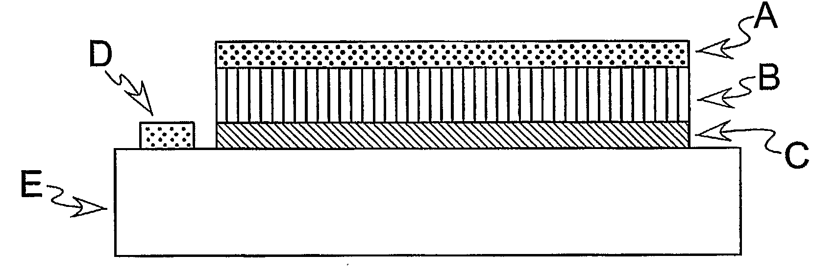
[0035]A schematic illustration of one embodiment of the invention is shown in FIG. 5. FIG. 5 shows a three-layer PSOFC anode where A is the sulfur-tolerant layer, B is the optimized H2 oxidation layer, C is a thin layer of Yttria Stabilized Zirconia that promotes ionic conduction, D is a reference electrode, and E is the electrolyte. The electrolytes of the PSOFCs used in the research can be made of scandia stabilized zirconia (SSZ) or YSZ.

[0036]In FIG. 6, a two layer preferred embodiment is shown in which A is the sulfur-tolerant layer, B is the optimized H2 oxidation layer, D is a reference electrode, and E is the electrolyte. The outer layer A is exposed to a flow of a fluid, which can be a liquid or a gas, such as a stream of gasified coal (syngas) containing a sulfur compound, such as H2S. The inner layer B preferably is not exposed directly to the fluid flow path, but all chemicals in the fluid preferably have to diffuse through the layer A to come into contact with the layer ...


PUM

PropertyMeasurementUnit
weight percentaaaaaaaaaa
thickaaaaaaaaaa

Abstract

An anode for a solid oxide fuel cell. The anode is not harmed by sulfur-containing compounds, nor is its resistance increased thereby. The anode has two layers, including a “protective” layer (A) and a layer (B) that oxidizes molecular hydrogen The protective layer has a diffusion rate for molecular hydrogen that exceeds its diffusion rate for sulfur-containing compounds, and has an oxidation rate for sulfur-containing compounds that exceeds its oxidation rate for molecular hydrogen. The first anode layer can be selected fro the group of Lanthanum Strontium Titanate (LST) and Lanthanum Strontium Vanadate (LSV), and the second anode layer is made of Gadolinium Doped Cerium oxide (GDC) and nickel. The first layer can include Yttria Stabilized Ziroonia (YSZ), and the second layer can include YSZ interspersed throughout the layer as a separate phase.

Description

BACKGROUND OF THE INVENTION[0001]This invention relates generally to fuel cell electrodes, and more particularly to an anode for a solid oxide fuel cell.DESCRIPTION OF THE RELATED ART[0002]A planar solid oxide fuel cell (PSOFC) contains two planar electrodes that sandwich a planar electrolyte and typically operate in a temperature range of 600° C. to 1000° C. (see FIG. 2). The anode is typically made of a nickel (Ni) / yttria stabilized zirconia (YSZ) cermet, the cathode is typically made of a strontium doped lanthanum manganite (LSM), and the electrolyte is made of a 3 or 8 mol % YSZ. The PSOFC converts chemical energy into electrical energy through the following two reactions shown in Equations 1 and 2.H2+0.5O2→H2O  (1)CO+0.5O2→CO2  (2)[0003]The fuel gas which may contain H2, CO, or a combination of the two, is provided to the anode of the PSOFC and oxygen in the form of air is provided to the cathode side of the PSOFC. The H2 and CO that enter the anode are then electrochemically o...

Claims


Application Information

Patent Timeline
Patent Type & Authority Applications(United States)
IPC IPC(8): H01M4/00
CPCH01M4/8605H01M4/8657H01M4/9016H01M4/9033H01M4/9066Y02T90/32H01M8/1213H01M2004/027H01M2250/20Y02E60/521Y02E60/525H01M8/0675Y02E60/10Y02E60/50Y02T90/40H01M4/92H01M8/12
Inventor BAYLESS, DAVID J.TREMBLY, JASON P.
Owner OHIO UNIV
Why Eureka
Try Eureka