
Card-type electronic apparatus assembly using ultrasonic joining

a technology of electronic apparatus and ultrasonic joining, which is applied in the direction of electrical apparatus casings/cabinets/drawers, record carriers, mounting of support structures, etc., can solve the problems of form factor problems, difficult to accurately achieve a specific height hi value, and sd card form factor deviations, etc., to prevent the possibility of bonding material overflowing, minimize the chance of misalignment, and high-precision alignment tooling

Inactive Publication Date: 2008-10-07
SUPER TALENT TECH CORP
View PDF27 Cites 43 Cited by
  • Summary
  • Abstract
  • Description
  • Claims
  • Application Information

AI Technical Summary

Benefits of technology

[0012]The present invention is directed to a card-type electronic apparatus that is formed from upper and lower covers that are joined at a seam that is internal to the apparatus housing. This internal joining beneficially prevents bonding material from overflowing to the exterior of the apparatus, and also minimizes the chances of misalignment between the upper and lower covers (and at the same time eliminating the need for high-precision alignment tooling for assembly). The invention can be applied to any card-type electronic apparatus, including Secure Digital (SD) cards, CompactFlash (CF) cards, Memory Stick cards, and USB flash drives, among others.
[0014]Bonding between the upper cover and lower cover takes place within this pocket region, so that the sidewalls of the lower cover beneficially prevent melted bonding material from flowing to the exterior of the apparatus. In addition, since the sides of the card-type electronic apparatus can be formed from just the sidewalls of the lower cover (rather than from a combination of sidewalls from both the upper and lower covers), control over the dimensional integrity of the apparatus can be more easily maintained.
[0015]According to an embodiment of the invention, the sidewalls of the lower cover can be a slip fit with the upper cover, thereby simple assembly and re-assembly prior to ultrasonic bonding. According to another embodiment of the invention, the sidewalls of the lower cover can be an interference fit with the upper cover, thereby providing improved bonding between the upper and lower covers for enhanced durability.
[0016]According to an embodiment of the invention, the sidewalls of the lower cover completely surround the upper cover, thereby providing total positioning and alignment of the upper cover relative to the lower cover. According to another embodiment of the invention, the sidewalls of the lower cover only partially surround the upper cover, thereby enabling greater assembly flexibility.

Problems solved by technology

Unfortunately, the SD card 100 formed using conventional upper cover 110 and lower cover 120 can exhibit problematic deviations from the optimal SD card form factor.
Furthermore, because the height Hi of SD card 100 is determined by the combined heights of upper sidewalls 111 and lower sidewalls 121 (and any residual bonding material between the two), accurately achieving a specific value for height Hi can be difficult.
In addition, the flow of bonders 141 as they melt during the ultrasonic joining process can cause form factor problems.

Method used


Image

  • Card-type electronic apparatus assembly using ultrasonic joining
  • Card-type electronic apparatus assembly using ultrasonic joining
  • Card-type electronic apparatus assembly using ultrasonic joining

Examples


Embodiment Construction

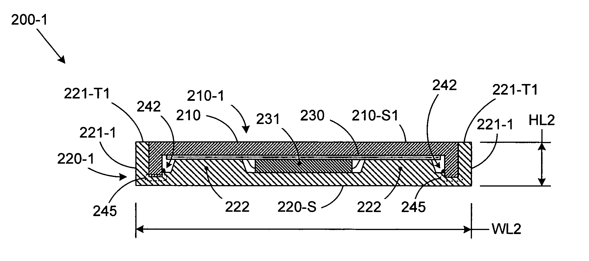
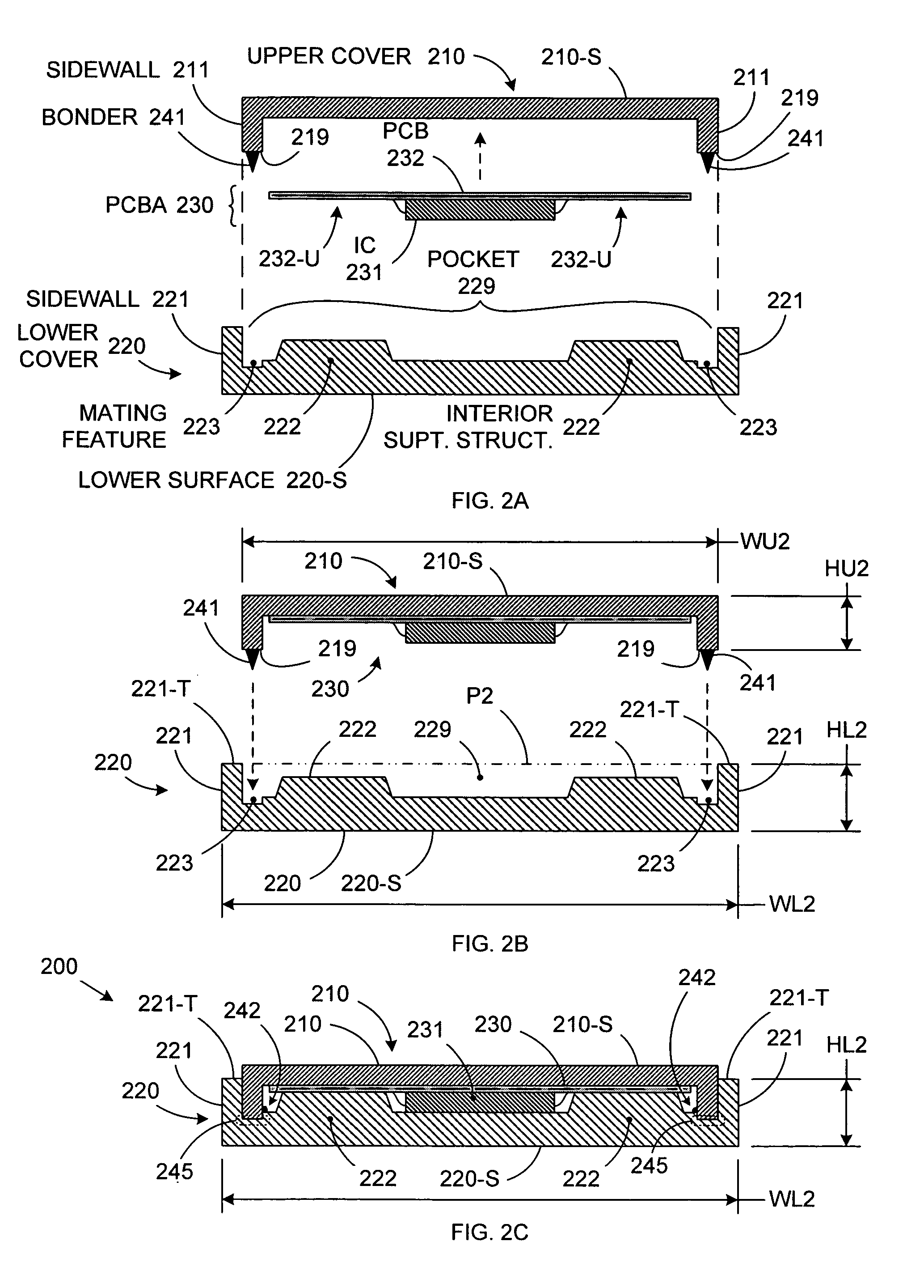
[0028]FIGS. 2A, 2B, and 2C show an assembly process for a card-type electronic apparatus, according to an embodiment of the invention. As depicted in FIG. 2A, the card-type electronic apparatus includes an upper cover 210, a lower cover 220, and a PCBA 230. PCBA 230 includes one or more ICs 231 and / or other electronic components mounted on a PCB 232. Upper cover 210 includes upper sidewalls 211 that extend substantially perpendicularly away from a substantially planar upper (external) surface 210-S of upper surface 210. Sidewalls 211 run along at least two edges of upper cover 210, and multiple ultrasonic bonders 241 are attached to various locations on mating surfaces 219 of sidewalls 211. Meanwhile, lower cover 220 includes lower sidewalls 221 that extend substantially perpendicularly from a substantially planar lower (external) surface 220-S of lower cover 220. Sidewalls 221 run along at least two edges of lower cover 220.

[0029]Unlike in conventional card-type device housings (su...


PUM

PropertyMeasurementUnit
Widthaaaaaaaaaa
Dimensionaaaaaaaaaa

Abstract

A card-type electronic apparatus such as an SD card, a CF card, a Memory Stick card, or a USB flash drive is formed from an upper and lower cover that are bonded together at an interior seam formed using ultrasonic joining. Lower sidewalls on the lower cover create an installation pocket for the upper cover. The installation pocket not only simplifies alignment between the upper and lower covers, but also contains any bonder material overflow that might otherwise affect the external dimensions of the apparatus housing. The lower sidewalls can completely surround the upper cover, for drop in installation. Alternatively, the lower sidewalls can partially surround the upper cover, so that the upper cover can be slid into place during assembly.

Description

BACKGROUND OF THE INVENTION[0001]1. Field of the Invention[0002]The invention relates to the field of electronic devices, and in particular, to a method and structure for accurately and neatly assembling a card-type electronic apparatus.[0003]2. Related Art[0004]A card-type electronic apparatus (such as a flash memory card or a PCMCIA card) is a computer component that can be used, for example, as a storage element, a communications interface, or an authentication device. A card-type electronic apparatus typically includes a small printed circuit board assembly (PCBA) encased in a durable housing. The PCBA can include various types of integrated circuits (ICs), such as flash memory or communications controllers.[0005]The form factors of the different card-type electronic apparatus housings are typically defined by a formal specification that provides detailed size, shape, and connectivity requirements. Card-type electronic apparatus housings must therefore be carefully controlled to...

Claims


Application Information

Patent Timeline
IPC IPC(8): H05K5/00
CPCH05K5/026B29C65/08B29C66/1142B29C66/124B29C66/131B29C66/3022B29C66/30223B29C66/5414B29C66/545B29L2017/00B29L2017/006
Inventor WANG, KUANG-YUHSUEH, PAULNI, JIM
Owner SUPER TALENT TECH CORP
Learn More