Apparatus, methods, systems, and articles incorporating a clock correction technique

a clock correction and multi-carrier technology, applied in the field of data communication systems, can solve the problems of complex loop timing, i.e. synchronization, and difficulty in providing synchronization between the adc and dac clocks running on the local transceiver side and the adc and dac clocks running on the remote transceiver sid

Inactive Publication Date: 2008-10-07
SASKEN COMMUNICATION TECHNOLOGIES
View PDF18 Cites 29 Cited by
  • Summary
  • Abstract
  • Description
  • Claims
  • Application Information

AI Technical Summary

Benefits of technology

[0011]The clock correction technique synchronizes both the frequency and phase of the local transceiver clock with those of the remote transceiver clock. This is achieved by having independent estimators for frequency offset and phase drift. Each of these estimates is then combined to form a single correction factor to the local transceiver clock and the resultant samples are again examined for any drifts in frequency or phase. Thus, a continuous feedback loop exists between the estimates and the corrections applied to the local sampling clock. This feedback process, without the need for complicated and computationally intensive fits to clock models, can handle just about any clock jitter or unmodelled effects in a clock.

Problems solved by technology

The problem with such a data communication system is that it is generally difficult to provide synchronization between the ADC and DAC clocks running on the local transceiver side and the ADC and DAC clocks running on the remote transceiver side.
The problem of loop timing, i.e. synchronization, is complicated by the presence of noise in the channel of a data communication system.
Additional impairments like drift in the clock frequencies at either transceiver side or clock jitter, can further compound the clock synchronization problem.
The problem of clock synchronization in data communication systems generally stems from a mismatch between remote transceiver and local transceiver clock frequencies.
Loss of clock synchronization typically leads to a loss of frame boundary synchronization, sample slippage, and a higher noise around received signals.
These can in turn lead to higher rates of bit errors and a decreased data throughput.
The scheme accounts for only frequency differences between the remote and local transceiver clocks, whereas in practice it is observed that frequency drift also results in a phase drift with respect to the remote transceiver clock.
This phase drift is of a magnitude and rate that, if uncorrected, could lead to sample slippage and thus loss of synchronism and consequently sub-optimal performance of the modem.
However, in practice it is observed that due to a drift in frequency in the remote and local transceivers, there is also a drift in phase between the remote and local transceiver clocks.
This phase drift is of such a magnitude and rate that if left uncorrected, could lead to sample slippage and thus lead to a loss of synchronization between the remote and local transceiver clocks, and consequently result in sub-optimal performance of the modems.

Method used


Image

  • Apparatus, methods, systems, and articles incorporating a clock correction technique
  • Apparatus, methods, systems, and articles incorporating a clock correction technique
  • Apparatus, methods, systems, and articles incorporating a clock correction technique

Examples


Embodiment Construction

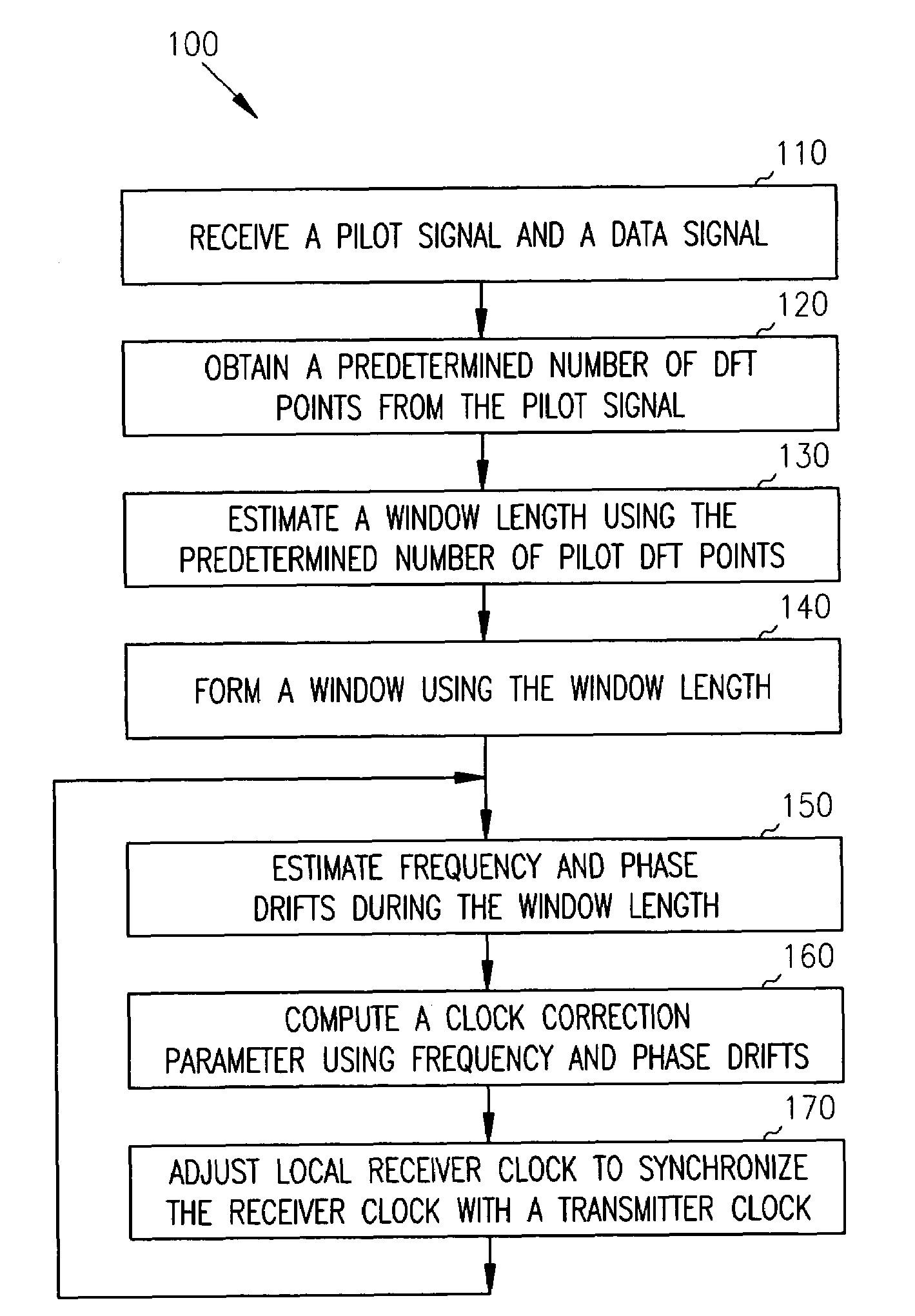
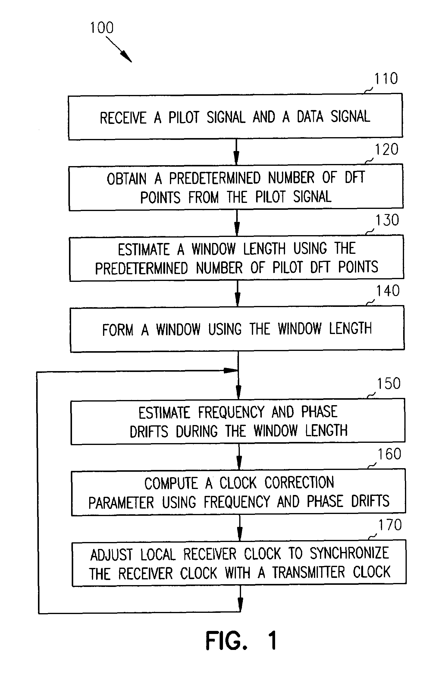
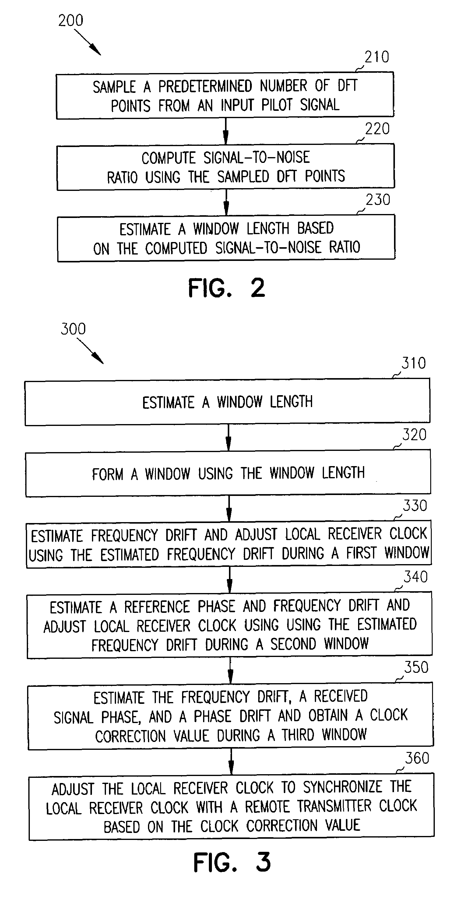
[0022]The present invention provides an improved clock correction technique for multi-carrier communication systems. In one embodiment, this is accomplished by estimating frequency and phase drifts between a local receiver clock and a remote transmitter clock using a pilot signal received by a local receiver. The local receiver clock is then adjusted using the estimated frequency and phase drifts to synchronize the local receiver clock with the remote transmitter clock to improve performance.

[0023]In the following detailed description of the embodiments of the invention, reference is made to the accompanying drawings that form a part hereof, and in which are shown by way of illustration specific embodiments in which the invention may be practiced. These embodiments are described in sufficient detail to enable those skilled in the art to practice the invention, and it is to be understood that other embodiments may be utilized and that changes may be made without departing from the sc...


PUM


Abstract

The present invention provides an improved clock correction scheme for multi-carrier transmission systems, based on synchronizing a local receiver with a remote transmitter using estimated phase and frequency drifts between the remote transmitter and local receiver clocks. Also, described are communication devices and methods.

Description

RELATED INVENTION [0001]The present invention is related to U.S. Pat. No. 6,577, 690, entitled “Clock recovery in multi-carrier transmission systems”, which is assigned to the assignee of the present invention and incorporated herein by reference.FIELD OF THE INVENTION[0002]This invention generally relates to data communication systems and more particularly to clock correction techniques for multi-carrier communication systems.BACKGROUND [0003]A data communication system that employs Frequency Division Multiplexed (FDM) sub carriers for transmission of data across a communication channel is termed a multi-carrier communication system. A data communication system generally has a remote transceiver, such as a central office (CO) side modem and a local transceiver, such as a customer premise (CP) side modem. A transceiver generally has both the transmitter and the receiver.[0004]In a data communication system, the remote and local transceivers have independent sampling clocks running t...

Claims


Application Information

Patent Timeline
Patent Type & Authority Patents(United States)
IPC IPC(8): H04L7/00H04L27/26
CPCH04L27/2662H04L27/2657H04L27/2675H04L27/261
Inventor NAGARAJA, SRIKANTH
Owner SASKEN COMMUNICATION TECHNOLOGIES
Why Eureka
Try Eureka