Excavator and a machine for material transfer

Active Publication Date: 2008-10-14
LEIBHERR HYDRAULIKBAGGER GMBH
View PDF15 Cites 49 Cited by
  • Summary
  • Abstract
  • Description
  • Claims
  • Application Information

AI Technical Summary

Benefits of technology

[0013]The solution of the initially presented object in accordance with the invention results in a series of advantages: The previously used main hydraulic cylinders can thus be dimensioned smaller. Less energy from the diesel engine is necessary overall for the lifting. Higher working speeds are possible. The

Problems solved by technology

However, this is only successful with limitations since the infeed pres

Method used


Image

  • Excavator and a machine for material transfer
  • Excavator and a machine for material transfer
  • Excavator and a machine for material transfer

Examples


Embodiment Construction

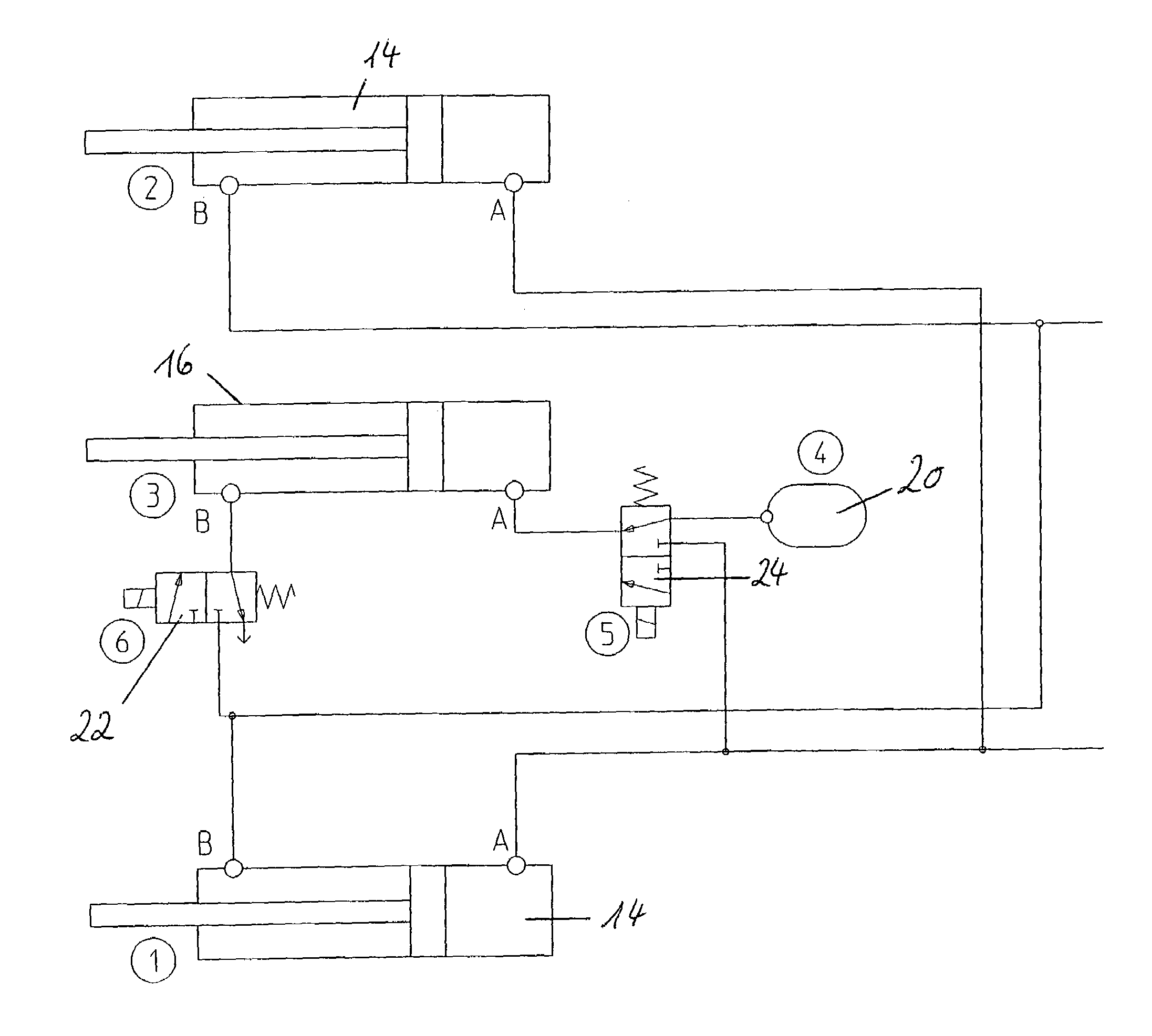
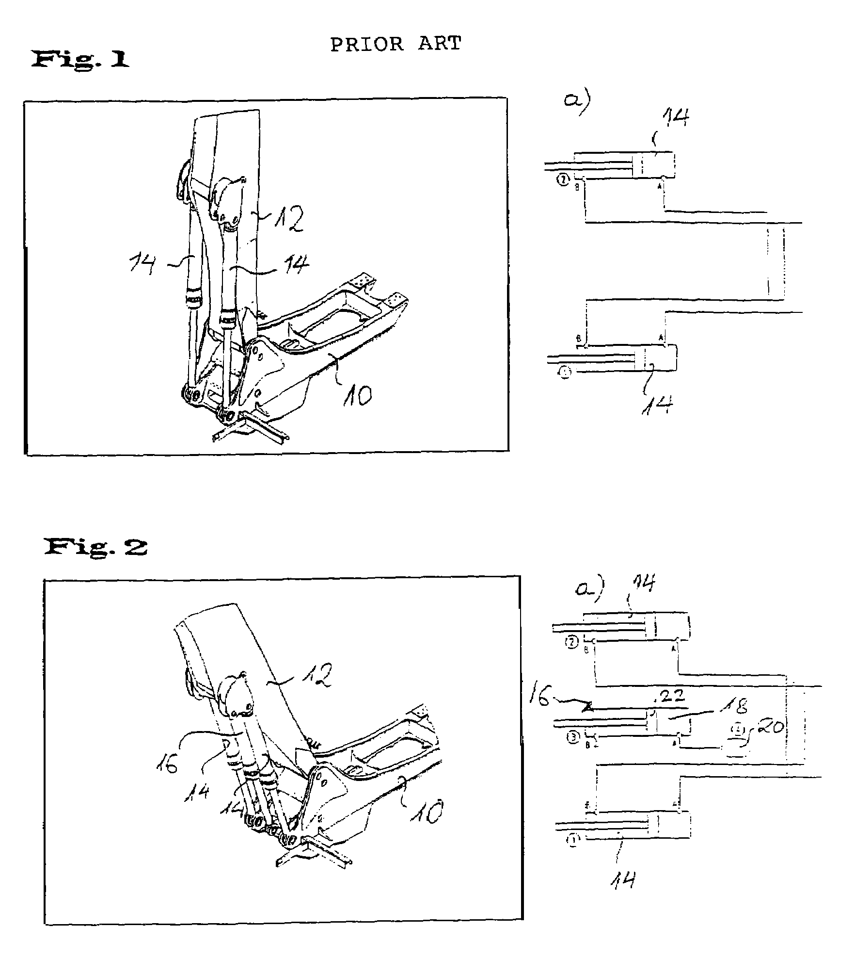
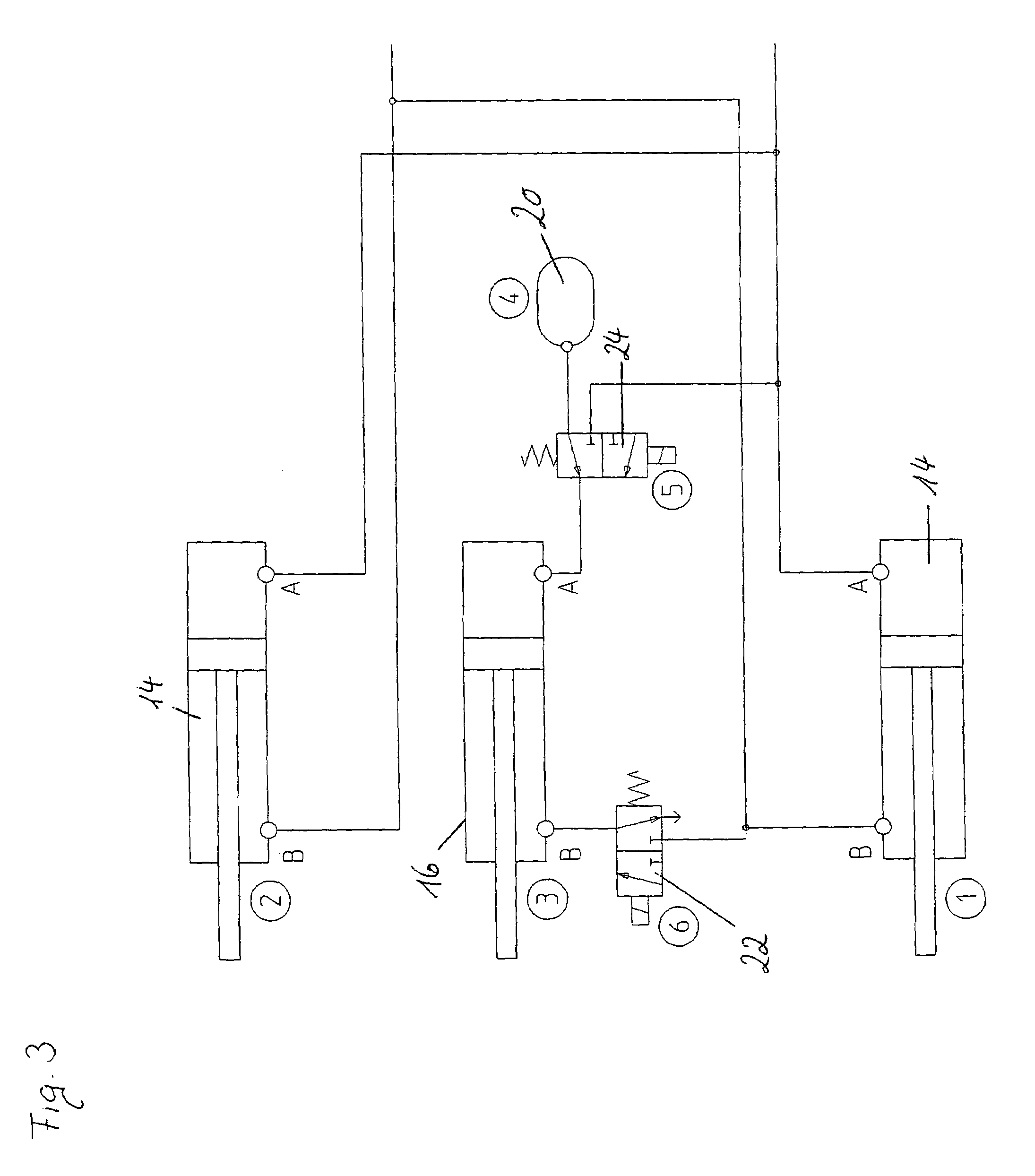
[0020]A detail of a hydraulic excavator is shown with reference to FIG. 2 by way of example for an excavator and machines for material transfer. Here, a boom 12 is pivotably hinged to a rotating deck 10, with the pivoting up and down of the boom 12 taking place via hydraulic cylinders 14. In addition to the hydraulic cylinders 14, an additional hydraulic cylinder 16 is arranged centrally. It can be seen from the hydraulic circuit diagram in accordance with FIG. 2a that the hydraulic cylinders 14 are connected to one another in a similar manner to that already known from the prior art (cf. FIG. 1a). In addition to the hydraulic cylinders 14, an additional hydraulic cylinder 16 is provided whose piston side 18 is connected to a hydraulic accumulator 20 which can, for example, be a piston accumulator or a bladder accumulator.

[0021]As can be seen from the hydraulic circuit in accordance with FIG. 2a, the additional hydraulic cylinder 16 is independent of the hydraulic cylinders 14. The ...


PUM


Abstract

The invention relates to an excavator or to a machine for material transfer comprising an element movable via at least one hydraulic cylinder. In accordance with the invention, one or more hydraulic cylinders are additionally hinged to the element, with the additional hydraulic cylinder(s) being connected to one or more hydraulic accumulators.

Description

BACKGROUND OF THE INVENTION[0001]The invention relates to excavators and to machines for material transfer comprising an element movable via at least one hydraulic cylinder.[0002]With excavators and machines for material transfer such as excavators, wheel-mounted loaders and similar plant, a boom and / or a shaft are moved e.g. via two parallel hydraulic cylinder pairs. In the case of an excavator, an attachment tool is then attached to the shaft and the good to be loaded is transferred with it. Both the boom and the shaft and the attachment tools naturally have masses. This means that only a small part of the energy used for the lifting work benefits the lifting of the load. The much greater part must be used for the lifting of the equipment and of the attachment tool.[0003]A detail of an excavator and of machines for material transfer in accordance with the prior art is shown by way of example in FIG. 1. It is an excavator in the present case. A boom 12 is hinged to a rotating deck ...

Claims


Application Information

Patent Timeline
IPC IPC(8): F16D31/02
CPCE02F9/2217F15B1/024F15B21/14
Inventor ASAM, DIRKMIEGER, ROLFWACHTER, ROLANDWAGER, BERND
Owner LEIBHERR HYDRAULIKBAGGER GMBH
Why Eureka
Try Eureka