Watertight gate having gate leaf connected to foldable support

a technology of gate leaf and foldable support, which is applied in the field of watertight gates, can solve the problems of gate b>4, major disadvantages, and overall efficiency reduction

Inactive Publication Date: 2008-10-14
UNIV COURT OF GLASGOW CALEDONIAN UNIV
View PDF73 Cites 12 Cited by
  • Summary
  • Abstract
  • Description
  • Claims
  • Application Information

AI Technical Summary

Benefits of technology

[0034]3) Periodically repeating the step of altering the foldable support structure so as to compensate for the effect of wear and tear of gate components on the efficiency of the watertight gate mechanism.

Problems solved by technology

Two major disadvantages have developed with the use of the aforementioned Mitre gates 4.
Therefore, the efficiency of the Mitre gate 4 is seasonally dependent and in general the overall efficiency is being reduced due to global warming effects.
The first solution is expensive, as a whole new gate is required along with major engineering to the surrounding area.
However, due to lack of use and regular maintenance such systems are prone to mechanical failure that is only discovered at the time when the gate is most needed.
The disadvantage of employing additional support struts is two-fold.
Secondly, it is generally deployed to the upper edge of the gate leaves, causing a pivotal action, and thus reducing the efficiency of the heel post, sill and Mitre post.
Although an improvement on the present form of Mitre gates, these systems are extremely expensive, as they require extensive engineering of the support structure so as to enable incorporation of the required sector recesses.
The second major disadvantage of the Mitre gates 4 is the requirement to be constructed to a high degree of tolerance.
In addition, wear and tear on the heel posts and the Mitre posts results during normal opening and closing of the gate 4.
This wear and tear tends to be uneven due to the load caused by the swinging weight of the gate being concentrated in particular areas and so the efficiency of the gate 4 deteriorates with use.

Method used


Image

  • Watertight gate having gate leaf connected to foldable support
  • Watertight gate having gate leaf connected to foldable support
  • Watertight gate having gate leaf connected to foldable support

Examples


third embodiment

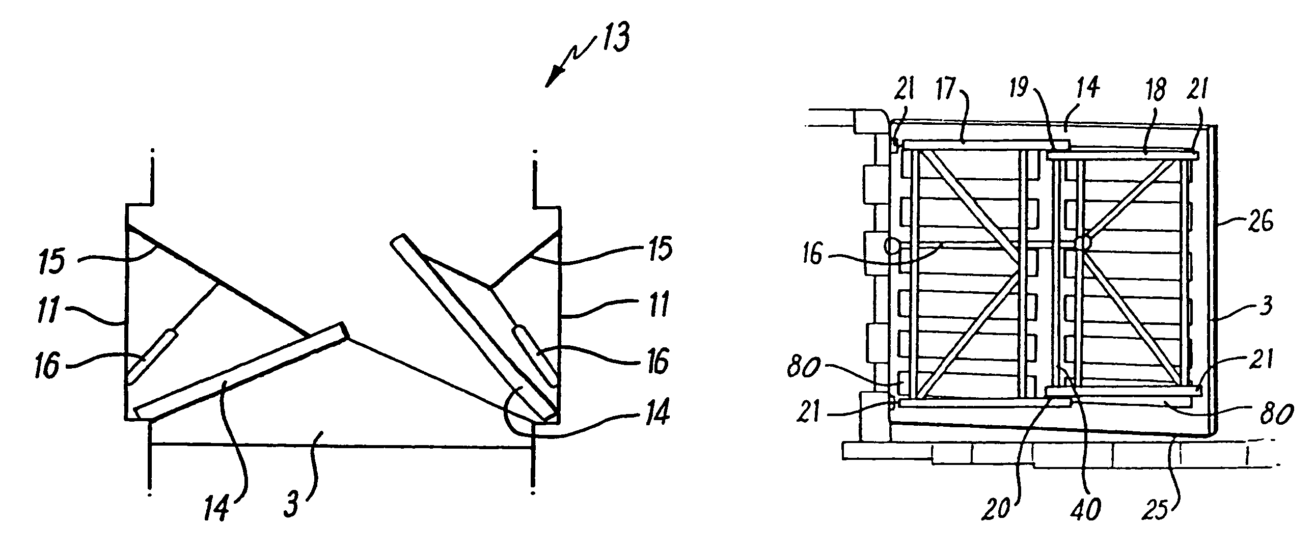
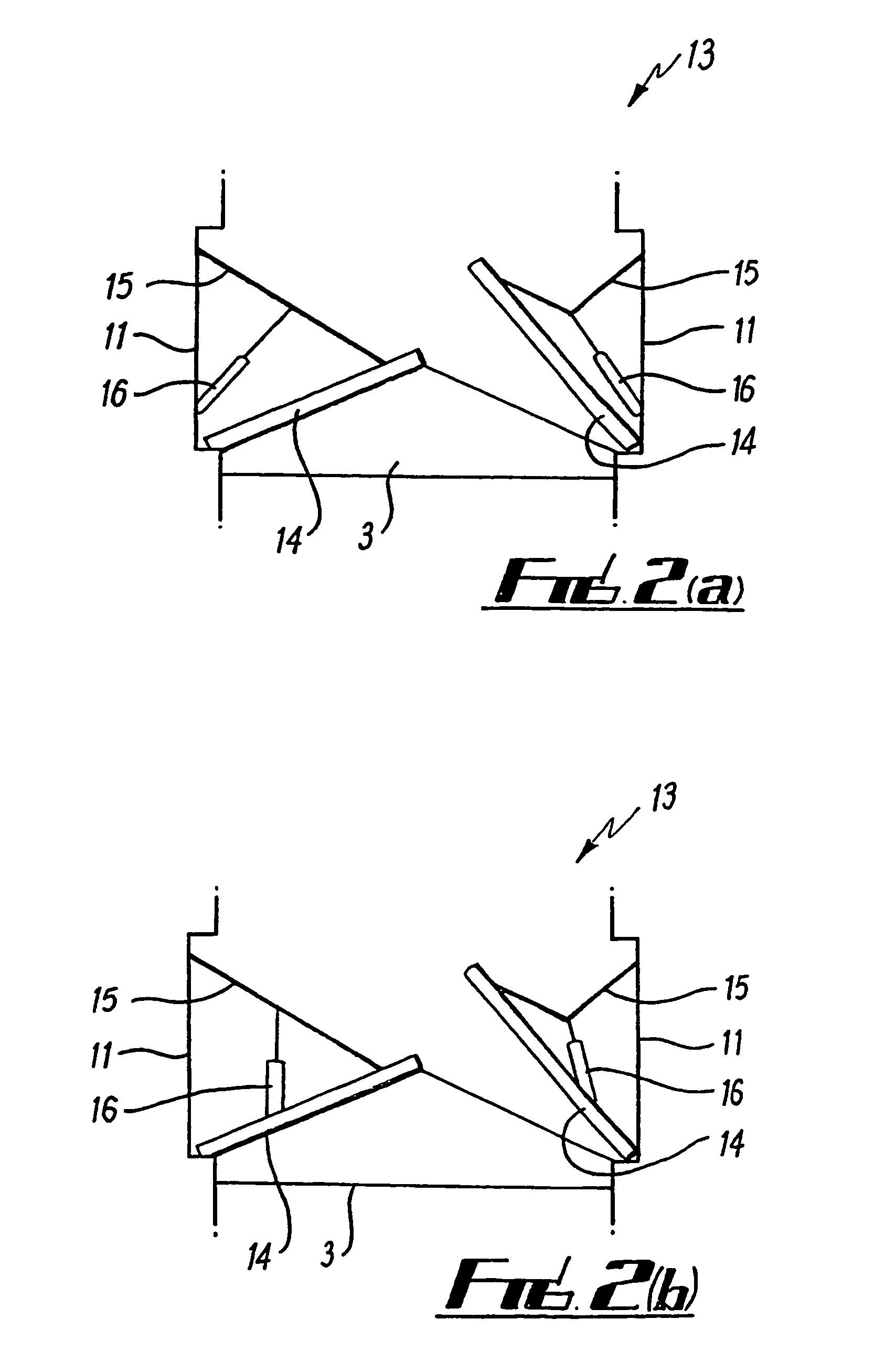
[0057]A third embodiment for the watertight gate mechanism 13 is presented in FIG. 2(c). Here the hydraulic control cylinder 16 is mounted completely within the gate recess 11 and is employed to operate an arm 15b that connects between the support structure 15 and a slidable mount (not shown). Thus as the hydraulic control cylinder 16 moves between a fully extended position and a fully retracted position the gate leave 5 moves between it's closed and open positions, respectively.

fourth embodiment

[0058]A fourth embodiment for the watertight gate mechanism 13 is presented in FIG. 2(d). In this embodiment a motor 16b mounted within the gate recess 11 is employed to control the angle of the section of the support structure 15 connected to the motor 16b. Thus by varying this angle a gate leaf 5 can be moves between it's closed and open positions as appropriate.

[0059]In addition to the support structure 15 acting as a compact control means for the position of the gate leaf 14 it also provides support for the load experienced by the gate leaf 14. In particular the support structure 15 can act equally well in tension or compression so as to support the gate leaf 14 independently of the relative water levels on either side of the gate mechanism 13. As a direct consequence of the present design the hydraulic cylinder 16 does not itself experience a direct load. This offers the advantage of minimising the wear and tear on this controlling component.

[0060]FIG. 5 presents a schematic il...


PUM


Abstract

An improved watertight gate for use in a port or canal is described. The watertight gate generally comprising two gate leaves and associated with each gate leaf is a foldable support structure and a gate position controller. The gate position controller interacts with the foldable support structure so as to move the associated gate leaf between an open and a closed position. By employing the gate position controller and the foldable support structure to control the gates the efficiency of the watertight seal provided by the gate is independent of water pressure produced by the surrounding bodies of water. Adjustable mounts attach the foldable support structures. These adjustable mounts provide for adjustment of the alignment of the watertight gate so minimizing the problems of installation alignment and reduced efficiency through wear and tear.

Description

CROSS-REFERENCE TO RELATED APPLICATIONS[0001]This application is the national phase of International (PCT) Patent Application Serial No. PCT / GB02 / 05067, filed Nov. 11, 2002, published under PCT Article 21(2) in English, which claims priority to and the benefit of British Patent Application No. 0127216.0, filed Nov. 13, 2001, the disclosures of which are incorporated herein by reference.FIELD OF THE INVENTION[0002]The present invention relates to the field of watertight gates. In particular, it relates to watertight gates for use within a port or a canal lock system.BACKGROUND OF THE INVENTION[0003]Locks provide fairly simple devices that allow boats to go up and down from one level to another within a canal. A schematic representation of a canal lock 1 is presented in FIG. 1. The lock essentially consists of a watertight chamber 2, two gate sills 3 and two Mitre gates 4 located at either end of the chamber 2, themselves comprising of two gate leaves 5. Sluice valves 6, sluice chambe...

Claims


Application Information

Patent Timeline
Patent Type & Authority Patents(United States)
IPC IPC(8): E02C1/00E02B7/44E02B7/20
CPCE02B7/20
Inventor CULLEN, MARTIN
Owner UNIV COURT OF GLASGOW CALEDONIAN UNIV
Why Eureka
Try Eureka