Sealing device and method for turbomachinery

a sealing device and turbomachinery technology, applied in the direction of machines/engines, efficient propulsion technologies, liquid fuel engines, etc., can solve the problems of thermal discrepancy between the shroud and the rotor blade, reduce the work efficiency of the turbine stage, and reduce the compression efficiency

Active Publication Date: 2008-10-14
GENERAL ELECTRIC CO
View PDF10 Cites 66 Cited by
  • Summary
  • Abstract
  • Description
  • Claims
  • Application Information

AI Technical Summary

Problems solved by technology

In a turbine stage, any portion of the working fluid passing through the clearance between the tips of the rotor blades and the static shroud does no work on the rotor blades, and leads to a reduced work efficiency of the turbine stage.
Likewise, such leakage in a compressor stage leads to a reduced compression efficiency.
In such a case, the high temperature of the working fluid causes a thermal discrepancy between the shroud and the rotor blades, wherein the shroud is at a lower temperature than the rotor blades.
The clearance between the shroud and the blades decreases during this transient period as the components reach their steady state conditions and dimensions, and causes the interfacing surfaces to rub, thereby leading to rapid wear of the blade material.
This can also lead to interference between rotor blades and the shroud.
In certain applications, such as aircraft engines, mechanical forces during operation (such as take-off and landing) can result in similar clearance changes.
In such a system, during the transient period, the blade tip contacts or rubs against the shroud, causing the shroud material to abrade or flake off.
However, this abradable system suffers from the disadvantage of reduced life of the sealing material.
Also, previous abradable seals, even though various materials for the shroud have been proposed such as sintered metal, metal honeycombs and porous ceramics, have not provided a desirable flexibility.
After wear due to a transient condition, such as a thermal transient or shock loading, the gap or wear produced by the rub or contact is larger than the interference depth, due to tearing out, galling and spalling.
However, while brush seals generally work satisfactorily for steam turbines, and for compressor stages, where temperatures do not exceed 650 to 700 degrees centigrade, they may not be always suitable for first or second stage gas turbines, where the temperature can exceed 800 degrees centigrade.
Furthermore, such seals have an inherently porous nature due to their fibrous structure, and lead to leakage of the working fluid.
Brush seals are also known to be subject to wear due to the continuous rubbing between the bristles and the blade tips.
Moreover, the intermittent nature of certain shrouds may result in problems with bristles of such brush seals as the shroud crevices are contacted by the bristles.

Method used


Image

  • Sealing device and method for turbomachinery
  • Sealing device and method for turbomachinery
  • Sealing device and method for turbomachinery

Examples


Embodiment Construction

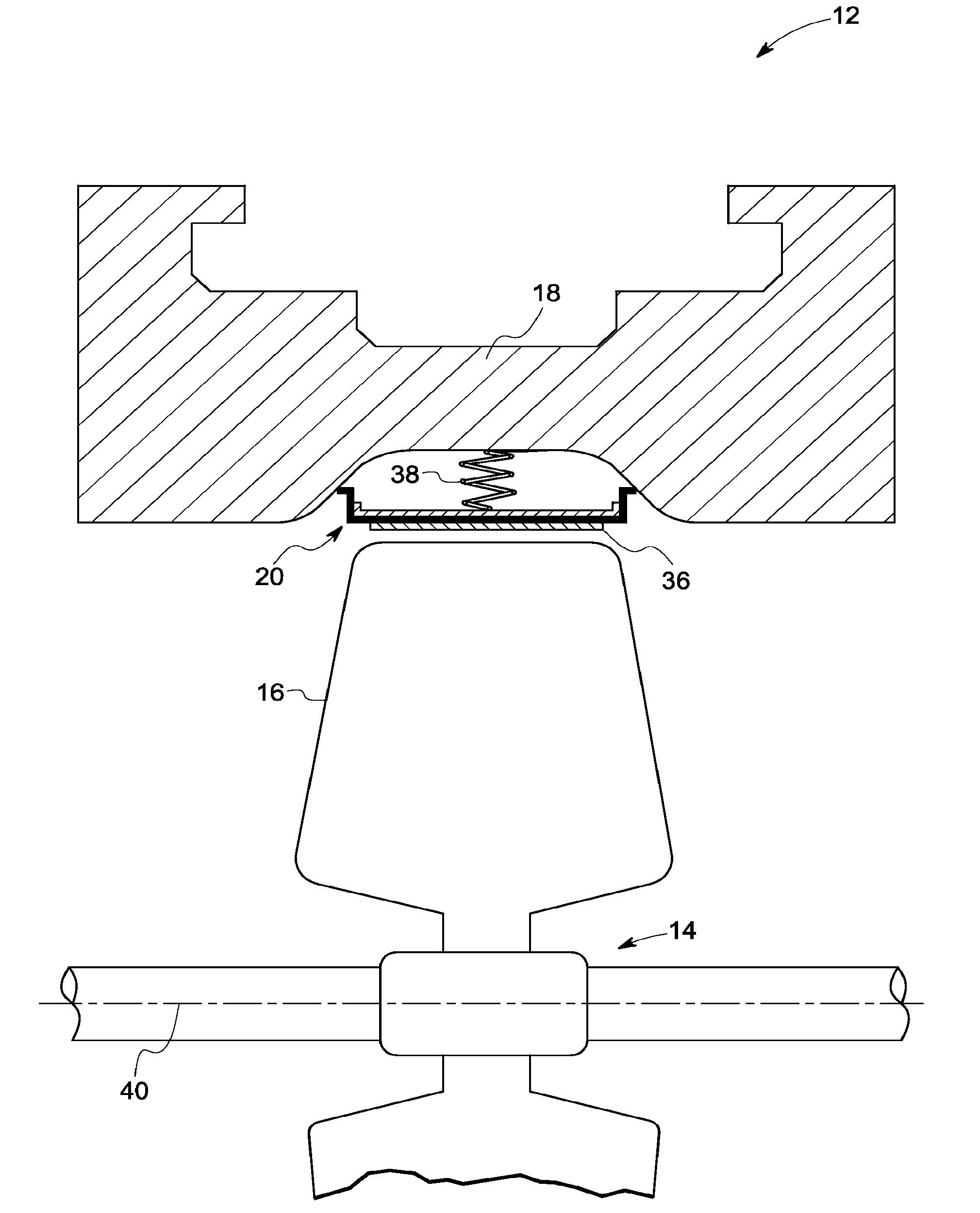
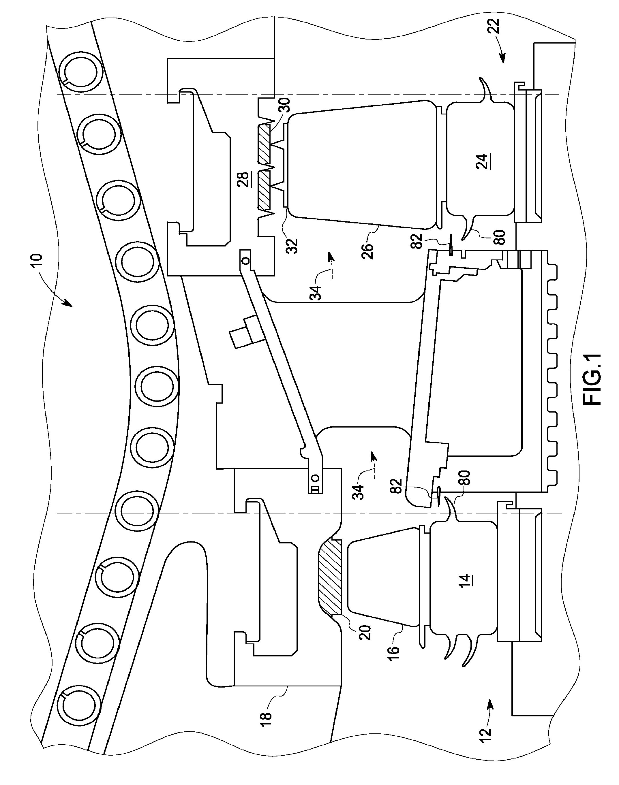
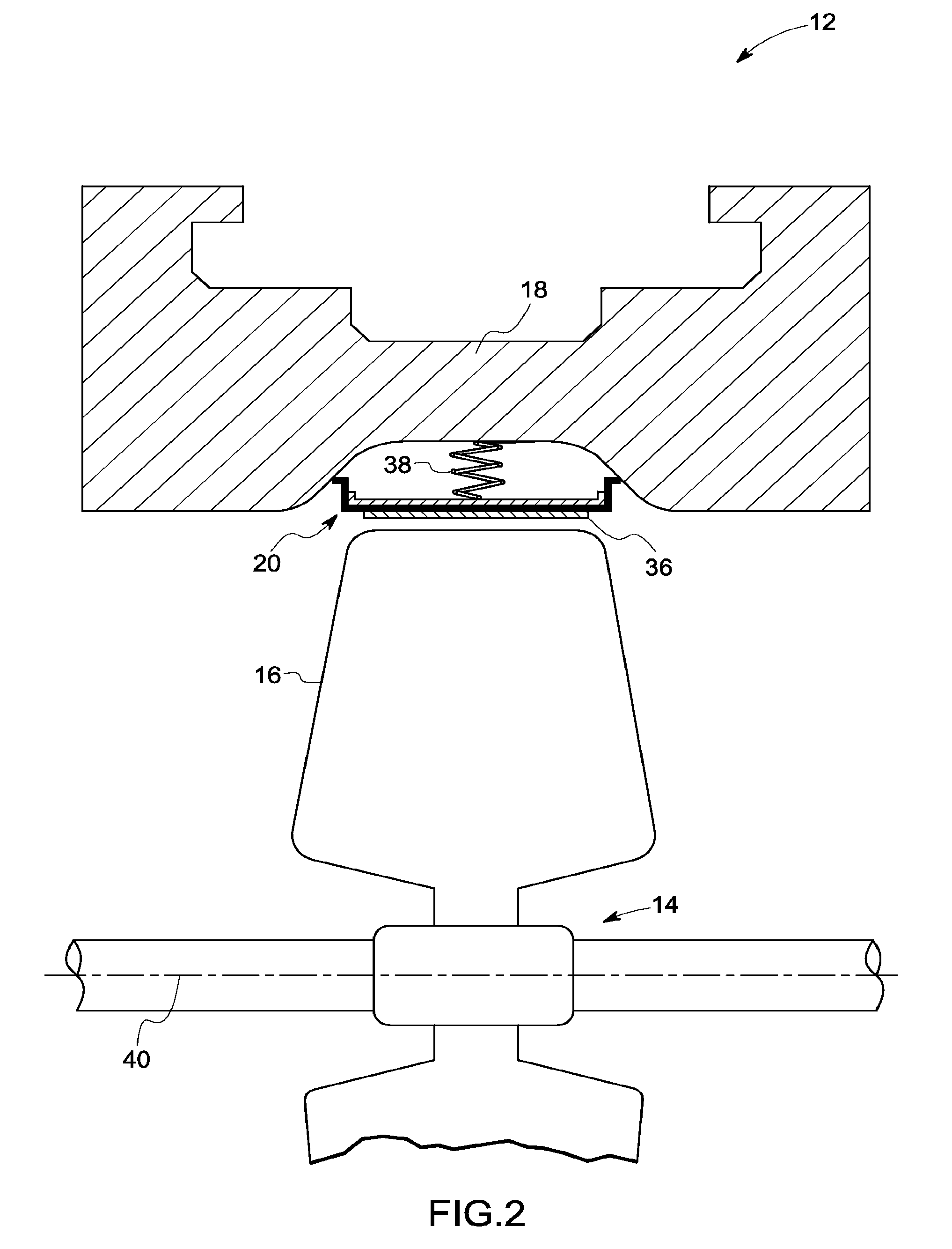
[0021]Referring now to FIG. 1, there is illustrated an exemplary portion of a turbine engine, designated generally by the reference numeral 10. Turbine 10 receives a hot gas, generated by an array of combustors (not shown in the figure), which transmit the hot gas along an annular hot gas path 34, as described below. Turbine stages 12, 22 are disposed along the annular hot gas path 34. Each such stage includes a rotor assembly, comprising a plurality of circumferentially spaced rotor blades or buckets, and a stationary shroud assembly. Each stage also includes a seal assembly for sealing a passage of the hot gas between tips of the rotating blades and the stationary shroud. For example, as shown, stage 12 comprises a rotor assembly 14, including a plurality of circumferentially spaced blades 16, a stationary shroud assembly 18, and a seal assembly 20 engaged at an interface of the rotating blades 16 and the stationary shroud 18. Similarly, stage 22 comprises a rotor assembly 24, inc...


PUM


Abstract

A compliant seal for use between rotating blades and a static shroud surrounding the rotating blades in a steam or gas turbine is disclosed. The seal includes a tip surface, substantially resistant to wear due to rubbing by the tip of the rotating blades, and an elastic biasing member, comprising a biasing element. The wear-resistant surface is thus biased against the tips of the rotating blades to seal a gas path between the rotating blades and the static shroud.

Description

BACKGROUND[0001]The present invention relates generally to the field of seals used in turbomachinery, and in particular to a compliant seal for application at the interface of a rotating component, such as the rotor blades in a turbine, and a stationary component, such as a shroud in a turbine.[0002]A number of applications call for sealing arrangements between rotating and stationary components. Such seals may vary in construction, depending upon such factors as the environments in which they function, the fluids against which they form a seal, and the temperature ranges in which they are anticipated to operate. In turbine and similar applications, for example, seals are generally provided between the various stages of rotating components, such as turbine blades, and corresponding stationary structures, such as housings or shrouds within which the rotating components turn.[0003]Efficiency and performance of gas and steam turbines are affected by clearances between rotor blade tips ...

Claims


Application Information

Patent Timeline
Patent Type & Authority Patents(United States)
IPC IPC(8): F01D11/06F01D5/28F01D11/12F01D11/08F01D11/14F02C7/28
CPCF01D5/225F01D11/14Y02T50/673Y02T50/60
Inventor GHASRIPOOR, FARSHADLOKHANDWALLA, MURTUZACHUPP, RAYMOND EDWARDBHATE, NITIN
Owner GENERAL ELECTRIC CO
Why Eureka
Try Eureka