Pool cleaning vacuum employing multiple power supply sources and associated method

a technology of power supply source and vacuum, which is applied in the direction of cleaning filter means, swimming pools, cleaning equipment, etc., can solve the problems of insufficient vacuum produced by the filter assembly, other debris sinking to the bottom of the pool and not being cleaned, and requiring additional time and effor

Inactive Publication Date: 2008-10-21
AJELLO MIKE
View PDF6 Cites 18 Cited by
  • Summary
  • Abstract
  • Description
  • Claims
  • Application Information

AI Technical Summary

Benefits of technology

[0019]The filter section includes a canister, and a cylindrical filter member conveniently housed within the canister. A one-way check valve automatically pivots between open and closed positions when the motor assembly is toggled to on and off positions. Such a filter member has axially opposed ends directly coupled to the one-way check valve and the motor assembly respectively for effectively directing the unfiltered water through the filter and out from the body via the gills.
[0020]A method for cleaning a bottom surface of an aqueous environment includes the steps of providing a body including first, second and third vertically juxtaposed chambers formed therein. Each of such first and third chambers share a wall with the second chamber wherein the third chamber is isolated from the first and second chambers such that water is prohibited from entering the third chamber when the body is submerged into the aqueous environment. The steps further include providing a motor assembly housed within the first chamber, providing a filter section housed within the first chamber and located downstream of the motor assembly, positioning a rigid and rectilinear anchor shaft within the second chamber and through an entire longitudinal length of the body, pivotally attaching a vacuum head directly to the anchor shaft, and automatically and continuously transmitting a predetermined quantity of power to the motor assembly such that a user can continuously operate the vacuum cleaner while receiving power from alternate sources.

Problems solved by technology

Other debris sinks to the bottom of the pool and is not cleaned during water recycling and filtration.
However, the vacuum produced by the filter assembly may be insufficient unless the filter is backwashed.
This requires additional time and effort.
These alterations to the filter system are time consuming and inconvenient.
Moreover, the repetitive disassembly and reassembly of filter connections imposes unwanted wear and tear on the filter components.
Unfortunately, this prior art example requires the availability of an AC power source nearby.
In addition, this example requires the use of electrical cords which may present a tripping hazard to a user during operating conditions.
Unfortunately, this prior art example does not include a multitude of power supply means including a rechargeable battery pack, a DC battery cell, and an electrical cord suitable for plugging into an existing AC power supply.

Method used


Image

  • Pool cleaning vacuum employing multiple power supply sources and associated method
  • Pool cleaning vacuum employing multiple power supply sources and associated method
  • Pool cleaning vacuum employing multiple power supply sources and associated method

Examples


Embodiment Construction

[0034]The present invention will now be described more fully hereinafter with reference to the accompanying drawings, in which a preferred embodiment of the invention is shown. This invention may, however, be embodied in many different forms and should not be construed as limited to the embodiment set forth herein. Rather, this embodiment is provided so that this application will be thorough and complete, and will fully convey the true scope of the invention to those skilled in the art. Like numbers refer to like elements throughout the figures.

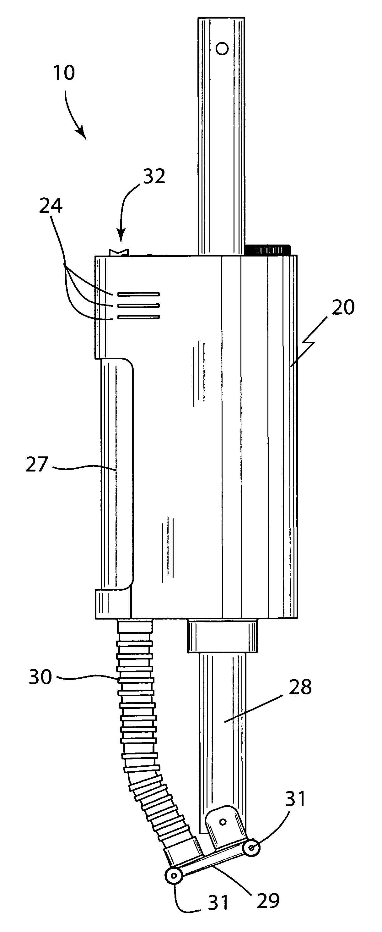
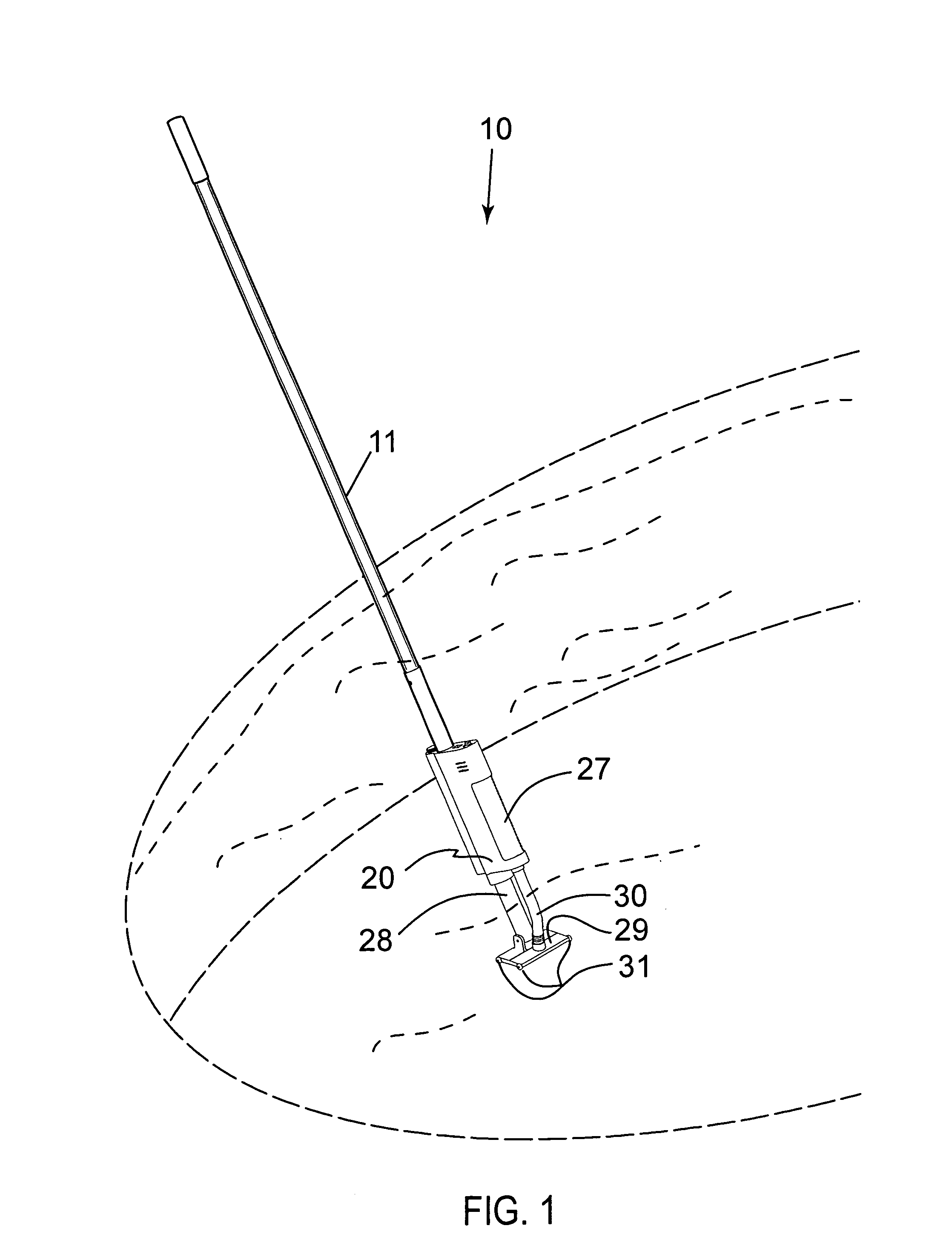
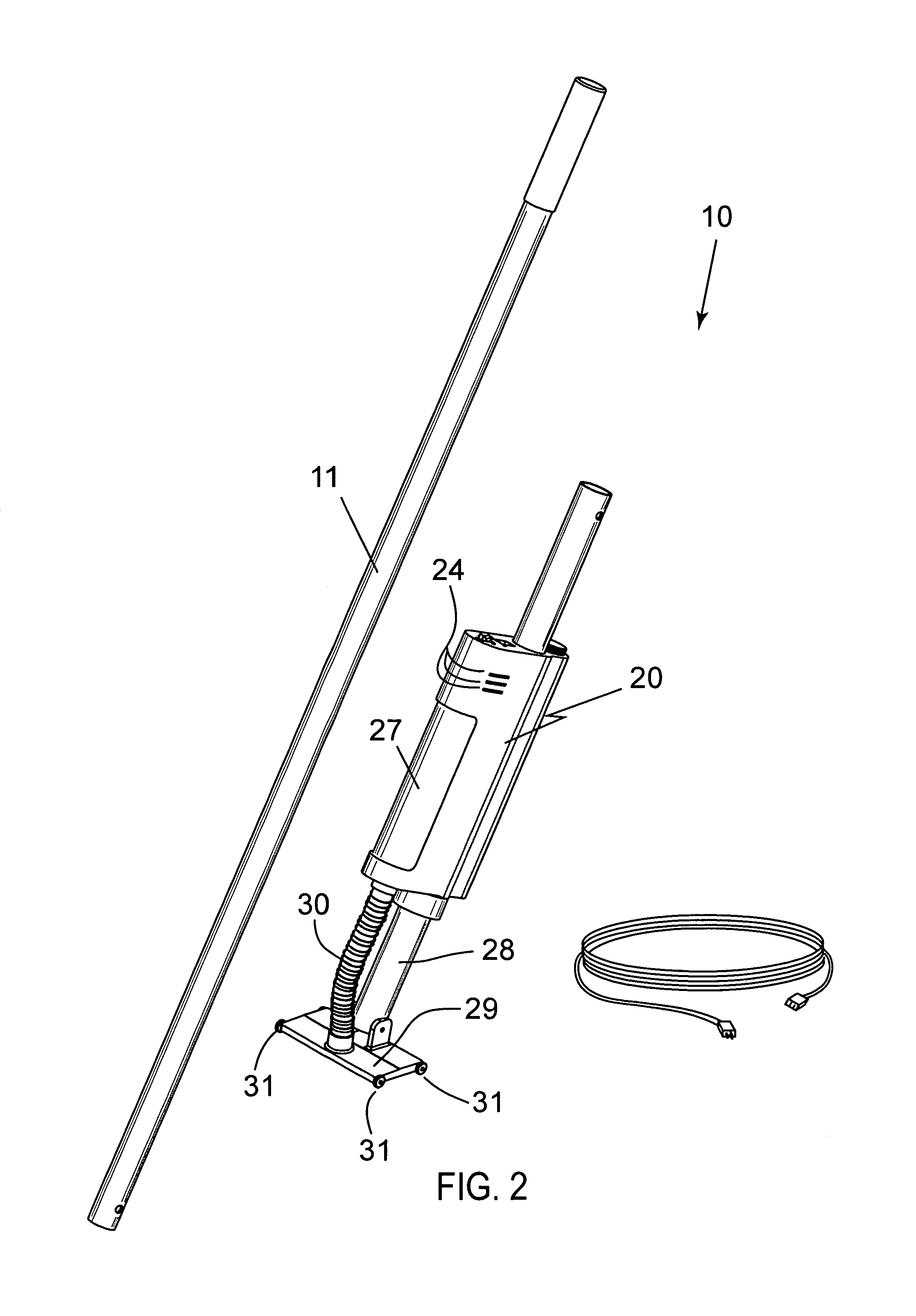
[0035]The apparatus of this invention is referred to generally in FIGS. 1-9 by the reference numeral10 and is intended to provide a pool cleaning vacuum employing multiple power supply sources and associated method. It should be understood that the apparatus 10 may be used to clean many different types of aqueous environments and should not be limited in use to cleaning only those types of aqueous environments described herein.

[0036]Referring...


PUM

PropertyMeasurementUnit
constant voltageaaaaaaaaaa
output voltageaaaaaaaaaa

Abstract

A pool cleaning vacuum employing multiple power supply sources and associated method includes a body including first, second and third vertically juxtaposed chambers formed therein. The chambers share a wall with the second chamber wherein the third chamber is isolated therefrom. A motor assembly and a filter section are housed within the first chamber. The filter section is located downstream of the motor assembly, and has an open lateral face exposed to the aqueous environment. An anchor shaft is seated within the second chamber and extends through an entire longitudinal length of the body. A vacuum head is pivotally attached to the anchor shaft. The vacuum head includes a conduit in communication with the filter section, and a plurality of wheels rotatably coupled to opposed corners thereof. A mechanism transmits a predetermined quantity of power to the motor assembly.

Description

CROSS REFERENCE TO RELATED APPLICATIONS[0001]This application claims the benefit of U.S. Provisional Application No. 60 / 772,132, filed Feb. 13, 2006, the entire disclosures of which are incorporated herein by reference.STATEMENT REGARDING FEDERALLY SPONSORED RESEARCH OR DEVELOPMENT[0002]Not Applicable.REFERENCE TO A MICROFICHE APPENDIX[0003]Not Applicable.BACKGROUND OF THE INVENTION[0004]1. Technical Field[0005]This invention relates to pool vacuums and, more particularly, to a pool cleaning vacuum employing multiple power supply sources for supplying continuous power during intermittent applications.[0006]2. Prior Art[0007]Swimming pools accumulate debris over a period of time. Some of the debris is cleaned from the pool water as the water is recycled and filtered. Other debris sinks to the bottom of the pool and is not cleaned during water recycling and filtration. To clean the debris that sinks to the bottom of the pool, a swimming pool vacuum cleaner may be employed. One form of...

Claims


Application Information

Patent Timeline
Patent Type & Authority Patents(United States)
IPC IPC(8): E04H4/16
CPCE04H4/1636Y10T29/49009Y10T29/49011
Inventor AJELLO, MIKE
Owner AJELLO MIKE
Why Eureka
Try Eureka