Supercharge Your Innovation With Domain-Expert AI Agents!

Gear having window holes, and method and apparatus for manufacturing the same

a technology of window holes and window holes, which is applied in the direction of hoisting equipment, other domestic objects, transportation and packaging, etc., can solve the problems of difficulty in obtaining the accuracy of the hole forming phase, the pitch of the hole against the clutch gear, and the cost of drilling and reamer processes that are much higher, so as to improve precision or accuracy, enlarge the degree of freedom of profile of window holes, and improve the degree of freedom of profil

Active Publication Date: 2008-10-21
O OKA CORP
View PDF10 Cites 3 Cited by
  • Summary
  • Abstract
  • Description
  • Claims
  • Application Information

AI Technical Summary

Benefits of technology

"The present invention relates to a gear with window holes that have improved tooth forms and a method for manufacturing the gear. The technical effects of the invention include minimizing the impact on tooth forms, increasing the number of window holes, and improving precision. The invention also includes methods for depressing one end surface of a primary formed article to form concavities for window holes and cutting protruding projections. The invention also includes apparatus for manufacturing the gear with window holes using forging and drag tools. Overall, the invention provides a more efficient and effective solution for gears with window holes."

Problems solved by technology

Drilling and reamer processes need a much greater expense for providing equipment for these processes and consumable tools and the forms for the window holes are limited to circular holes.
Moreover, because the clutch gear and the circular hole are formed in different processes, it is difficult to obtain accuracy of the hole forming phase i.e. the pitch of holes against the clutch gear.
Furthermore, because cutting scraps become attached and weld flashes occur, it is difficult to secure quality and uniformity of products.
In milling cutter and broaching, the forms of window holes used are not limited to circular holes, but those process have problems in that as wear and tear on the equipment occurs and the need for tools specific to cutting, inefficiency, the occurrence of cutting scraps and weld flashes, the difficulty of securing hole phases against the clutch gear and the requirement of providing a clearance for tools used in the processes must be taken into account.
Therefore, in those processes, products often have defects in terms of strength.
Therefore, it is necessary to rework the gear by cutting in order to delete the weld flash after blanking and the structure of a die for blanking is complex in order to delete the potential for weld flash.
Furthermore, cutting during the reworking causes an interruption in cutting completion.
Therefore, the resultant tool life is short, the window holes are limited to being penetrated holes and it is difficult to maintain a uniform tooth form due to the difference in pressure strength between a tooth form formed near by the window hole and a tooth form formed far from the window hole, while blanking.

Method used


Image

  • Gear having window holes, and method and apparatus for manufacturing the same
  • Gear having window holes, and method and apparatus for manufacturing the same
  • Gear having window holes, and method and apparatus for manufacturing the same

Examples


embodiment

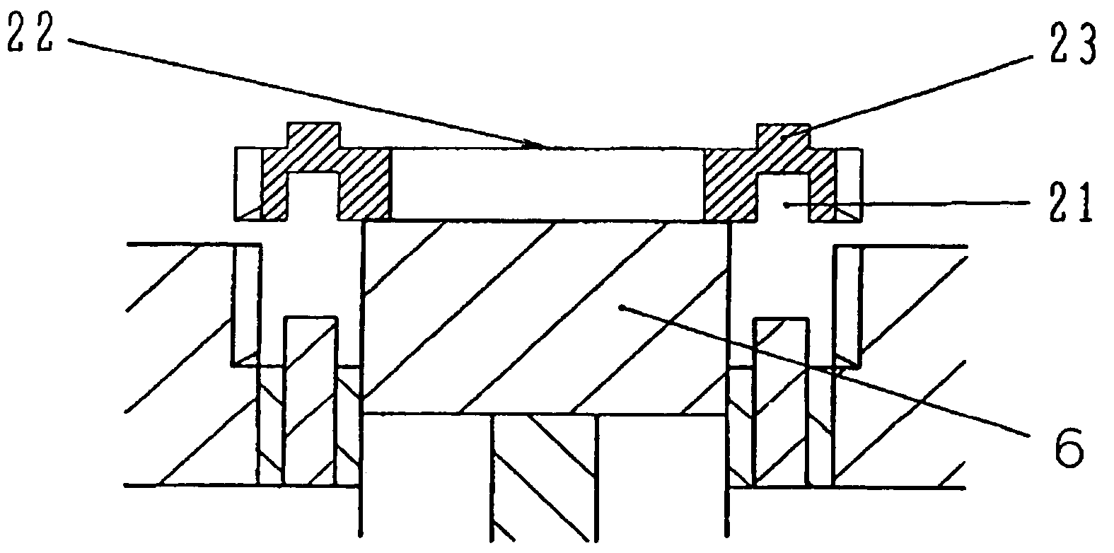
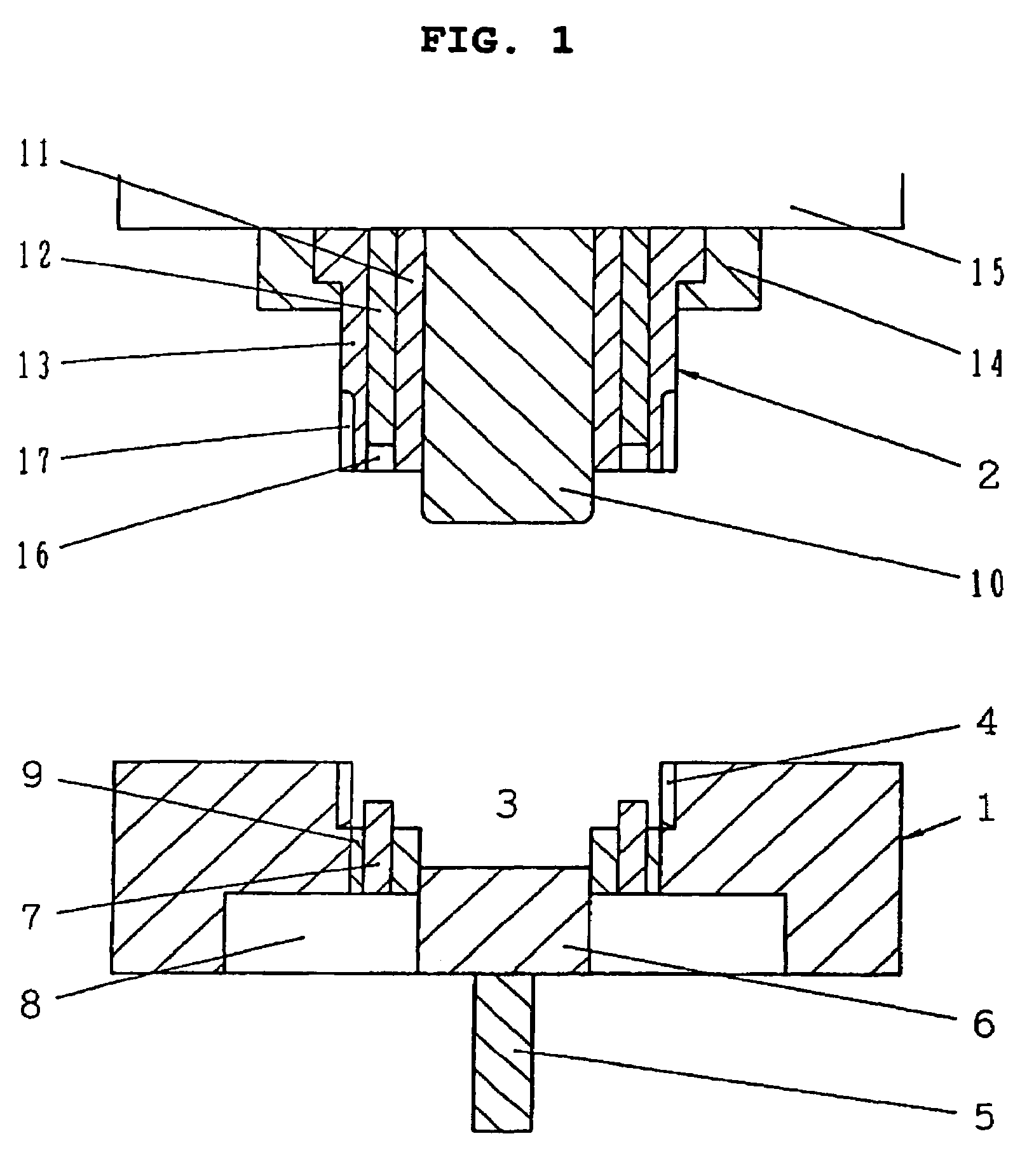
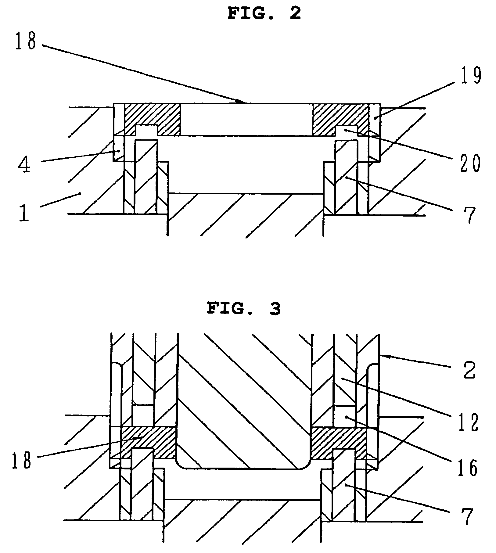
[0047]Gears having window holes, and the method and apparatus for manufacturing the same according to the embodiment of the present invention, are shown in FIGS. 1-5, in which by depressing partially one end surface of a primary formed article, a plurality of concavities for the window holes are formed at the one end surface in an axial direction of the primary formed articles, wherein a plurality of projections are extruded from the other end surface thereof, tooth forms preformed at an outer peripheral wall of the primary formed article are thrown out in radial direction thereof, and the gear is formed by cutting the plurality of projections extruded from the other end surface thereof.

[0048]FIG. 1 is an illustrative view illustrating an apparatus for manufacturing the gears. Reference number 1 is a drag member, and 2 denotes a cope. The drag 1 comprises tooth forms 4 for forming tooth forms on an inner circumferential surface of a cavity 3, ejectors 6 are arranged at a center of a...


PUM


Abstract

A gear having window holes, and method and apparatus for mafufacturing the same in which by depressing partially one end surface of a primary formed article, a plurality of concaves for the window holes is formed at the one end surface in an axial direction of the primary formed articles, a plurality of projections are extruded from the other end surface thereof and tooth forms preformed at an outer peripheral wall of the primary formed article is thrown out in radial direction thereof, and the gear is formed by cutting the plurality of projections extruded from the other end surface thereof.

Description

TECHNICAL FIELD[0001]This invention relates to gears having window holes such as a mulcher cone synchro mesh type clutch gear used for a manual transmission for an automobile and a method and apparatus for manufacturing the above described gears.TECHNICAL BACKGROUND[0002]A window hole of the gears having window holes are conventionally formed by forming a circular hole by drilling and reamer process, by boring by milling cutter and broaching or by blanking by press.[0003]Drilling and reamer processes need a much greater expense for providing equipment for these processes and consumable tools and the forms for the window holes are limited to circular holes. Therefore, the degrees of freedom of the diameter of a circular hole process and so on are restricted according to the diameter of a clutch gear.[0004]Moreover, because the clutch gear and the circular hole are formed in different processes, it is difficult to obtain accuracy of the hole forming phase i.e. the pitch of holes again...

Claims


Application Information

Patent Timeline
Patent Type & Authority Patents(United States)
IPC IPC(8): F16H55/08B21D53/28B21K1/30F16H55/17
CPCB21D53/28B21K1/30F16H55/17Y10T74/19851Y10T74/19972Y10T74/19949Y10T74/19963
Inventor OKADA, TOMOYOSHI
Owner O OKA CORP
Features
  • R&D
  • Intellectual Property
  • Life Sciences
  • Materials
  • Tech Scout
  • Unparalleled Data Quality
  • Higher Quality Content
  • 60% Fewer Hallucinations
Learn More