Gas supply arrangement of a marine vessel and method of providing gas in a marine vessel

a gas supply arrangement and marine technology, applied in the direction of load accommodation, special purpose vessels, container discharging methods, etc., can solve the problems of complicated arrangement and complicated control system, and achieve the effect of simple and space-saving installation and the number of required components

Active Publication Date: 2008-10-21
WARTSILA FINLAND OY
View PDF9 Cites 20 Cited by
  • Summary
  • Abstract
  • Description
  • Claims
  • Application Information

AI Technical Summary

Benefits of technology

[0014]The invention has several advantages. First of all, the number of required components is minimised, which leads to easy and space-saving installation. The pressure and gaseous gas production control is also very accurate due to the novel way of controlling the pressure. With the invention it is also possible to provide more suitable gas for gas engine operation by minimising the evaporation of the heavy hydrocarbons from the liquefied gas.

Problems solved by technology

However, the amount of natural boil-off gas is not sufficient for providing all propulsion energy required in all circumstances and therefore the vessel must be provided with additional means for acquiring extra gas, so called forced boil-off gas.
It is, however, somewhat complicated system requiring two parallel gas feed systems from the cargo tank to gas main supply line.
That kind of an arrangement requires also somewhat complicated control system.

Method used


Image

  • Gas supply arrangement of a marine vessel and method of providing gas in a marine vessel
  • Gas supply arrangement of a marine vessel and method of providing gas in a marine vessel

Examples


Embodiment Construction

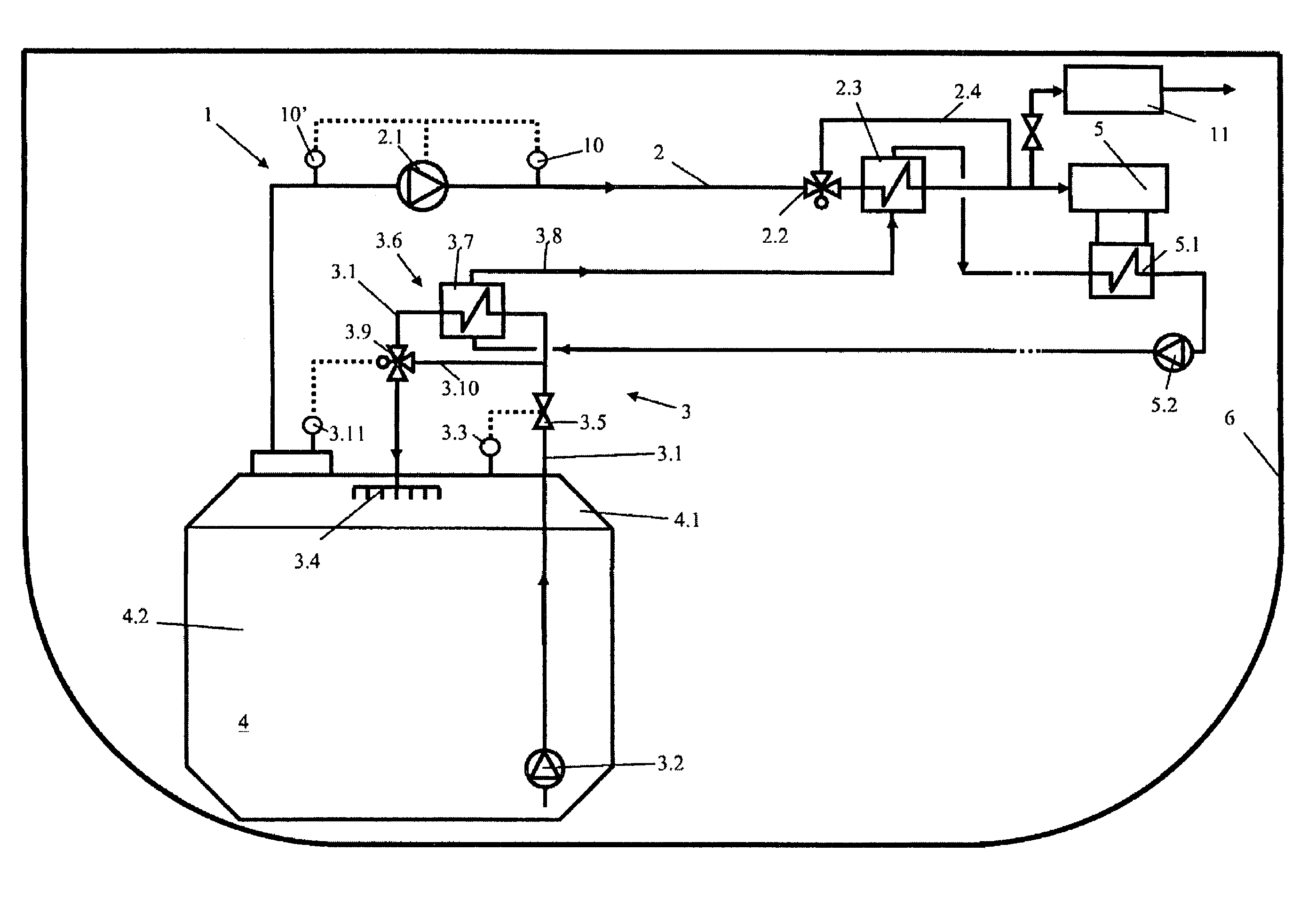
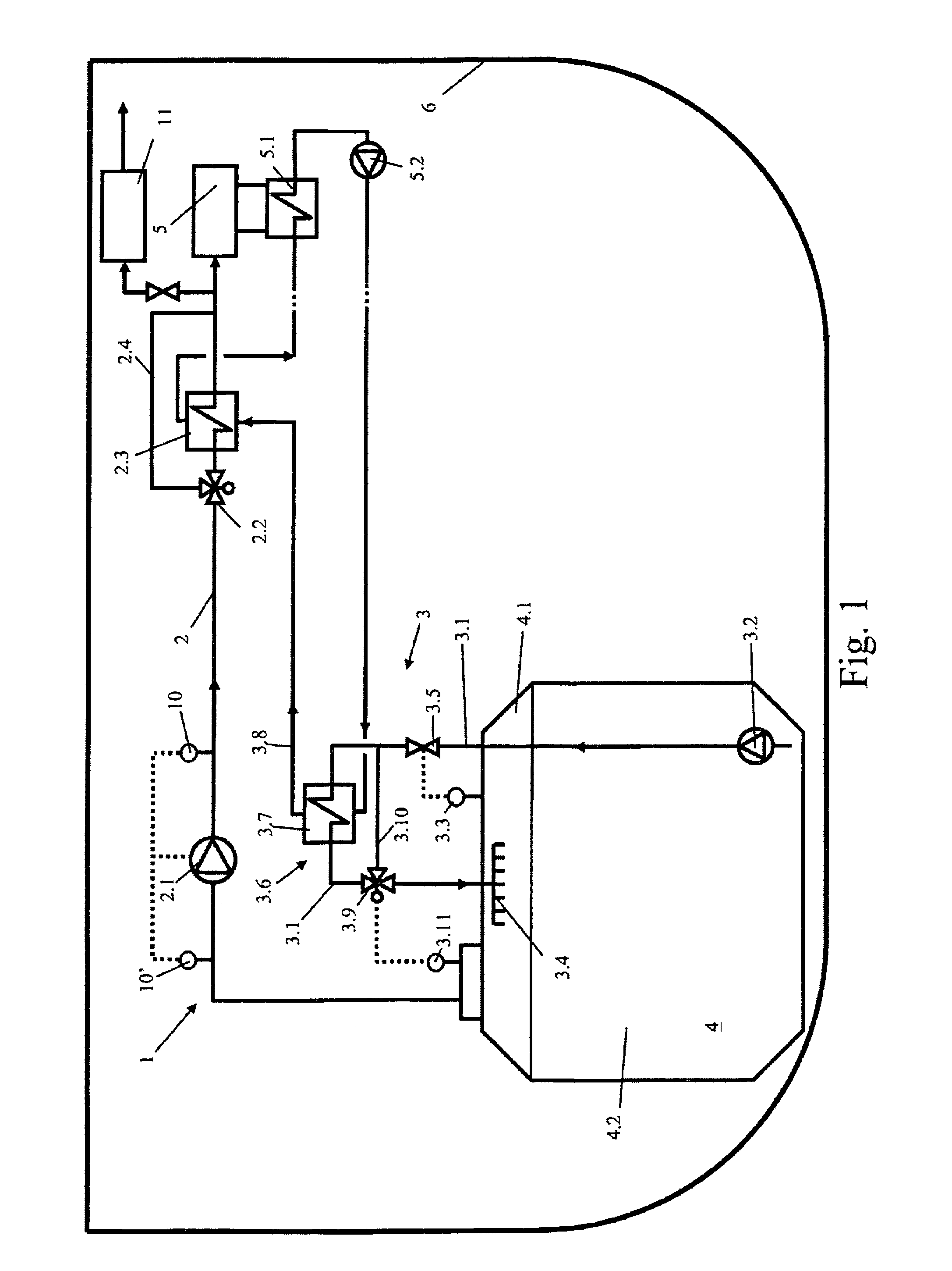
[0016]FIG. 1 depicts schematically cross section of a marine vessel 6, like LNG tanker. The vessel 6 is adapted to carry liquefied gas in its gas tanks 4. Normally there are several tanks in an LNG tanker, but in the figure only one gas tank 4 is shown for clarity reasons. The gas tank 4 is filled so that there is always an ullage space section 4.1 filled with gas in gaseous form and a liquid phase section 4.2 filled with liquefied gas. During the storing of the liquefied gas the gas is evaporating changing its phase and transferring to the ullage space 4.1 section. The evaporated gas may be utilised in a consumption device 5 of the vessel 6. The consumption device 5 may be e.g. a gas engine providing propulsion power for the vessel. In the FIG. 1 there is only one consumption device 5 is shown but it is clear that there may be several devices.

[0017]The vessel 6 is provided with a gas supply arrangement 1, which comprises a gas supply line 2 being provided with a compressor unit 2.1...


PUM


Abstract

Gas supply arrangement of a marine vessel being adapted to carry liquefied gas in its gas tank having an ullage space section and a liquid phase section, which arrangement provides the gas for demands of the vessel, the arrangement comprising a gas supply line provided for delivering the gas formed in the gas tank to a consumption device, and a piping extending from the liquid phase section to the ullage space section of the gas tank being provided with at least a pump, for introducing gas into the ullage space section. The piping is provided with a heat transfer unit for effecting on the temperature of the introduced gas. The invention relates also to method of providing gas in a marine vessel with liquefied gas tank.

Description

[0001]This is a national stage application filed under 35 USC 371 based on International Application No. PCT / FI2005 / 050072 filed Mar. 10, 2005, and claims priority under 35 USC 119 of Finnish Patent Application No. 20045081 filed Mar. 17, 2004.BACKGROUND OF THE INVENTION[0002]This invention relates to a gas supply arrangement of a marine vessel and to a method of providing gas in a gas supply arrangement of a marine vessel.[0003]The usage of gas as energy source in marine vessels is advantageous due to its efficient burning and low emissions. Usually gas is stored in liquefied form because less space is required for the storage that way.[0004]The propulsion system of LNG (Liquified Natural Gas) tankers is usually powered by making use of the cargo. Storing of the gas in the tanker is arranged by using heat insulated cargo tanks into which an ullage space section and a liquid phase section are formed. The pressure in the cargo tanks is approximately at atmospheric pressure level and ...

Claims


Application Information

Patent Timeline
Patent Type & Authority Patents(United States)
IPC IPC(8): B63B25/08B63J99/00F17C1/00F17C9/04
CPCB63J99/00F17C2265/03F17C9/00
Inventor KACKUR, JOHNNY
Owner WARTSILA FINLAND OY
Why Eureka
Try Eureka