System for treating a wound with suction and method of detecting loss of suction

a technology for wounds and suction sources, applied in the field of wound treatment, can solve the problems of practical limitations on the capacity of suction sources, and achieve the effects of reducing the likelihood of blood clotting in the line, preventing overfilling, and reducing the likelihood of reflux of contaminated fluid

Inactive Publication Date: 2008-10-21
PAUL HARTMANN AG
View PDF54 Cites 385 Cited by
  • Summary
  • Abstract
  • Description
  • Claims
  • Application Information

AI Technical Summary

Benefits of technology

[0014]By locating the vent in the conduit close to the wound, the reference airflow also serves to purge the conduit of fluids. The purging effect minimizes the likelihood of reflux of contaminated fluid back into the wound, and the risk of infection attendant to such reflux. Since the fluid does not reside in the conduit for an extended time, the purge effect also reduces the likelihood of blood clotting in the line.
[0015]The system may further include a waste collector, disposed in the suction line between the wound dressing and the source of suction, for collecting fluids aspirated from the wound. The preferred collector is an upright transparent plastic canister with fill level markings on the outside surface. The canister may be prevented from overfilling by a hydrophobic membrane filter at the top of the canister that shuts off the airflow when the canister is full. The liquids aspirated from the wound may be turned into a gel, for ease of disposal and to prevent spilling, by a gelling agent in the disposable canister. To keep the waste in the canister level, the gelling agent is preferably provided in stacked disks. The canister has an inlet connector for the suction tube from the wound dressing, and an outlet connector for connecting to a portable pump or to a flow monitoring instrument for use with stationary or hospital wall suction. The outlet connector is preferably a proprietary (non-standard) connector that will not connect directly to the standard appliance fitting of a stationary suction system, to prevent anyone from mistakenly connecting directly to the suction system.

Problems solved by technology

Higher flows such as 1000 cc / min are possible, but practical limitations on the capacity of the suction source as well as the magnitude of a leak in the dressing suggest that is preferable to use a flow below 1000 cc per minute.

Method used


Image

  • System for treating a wound with suction and method of detecting loss of suction
  • System for treating a wound with suction and method of detecting loss of suction
  • System for treating a wound with suction and method of detecting loss of suction

Examples


Embodiment Construction

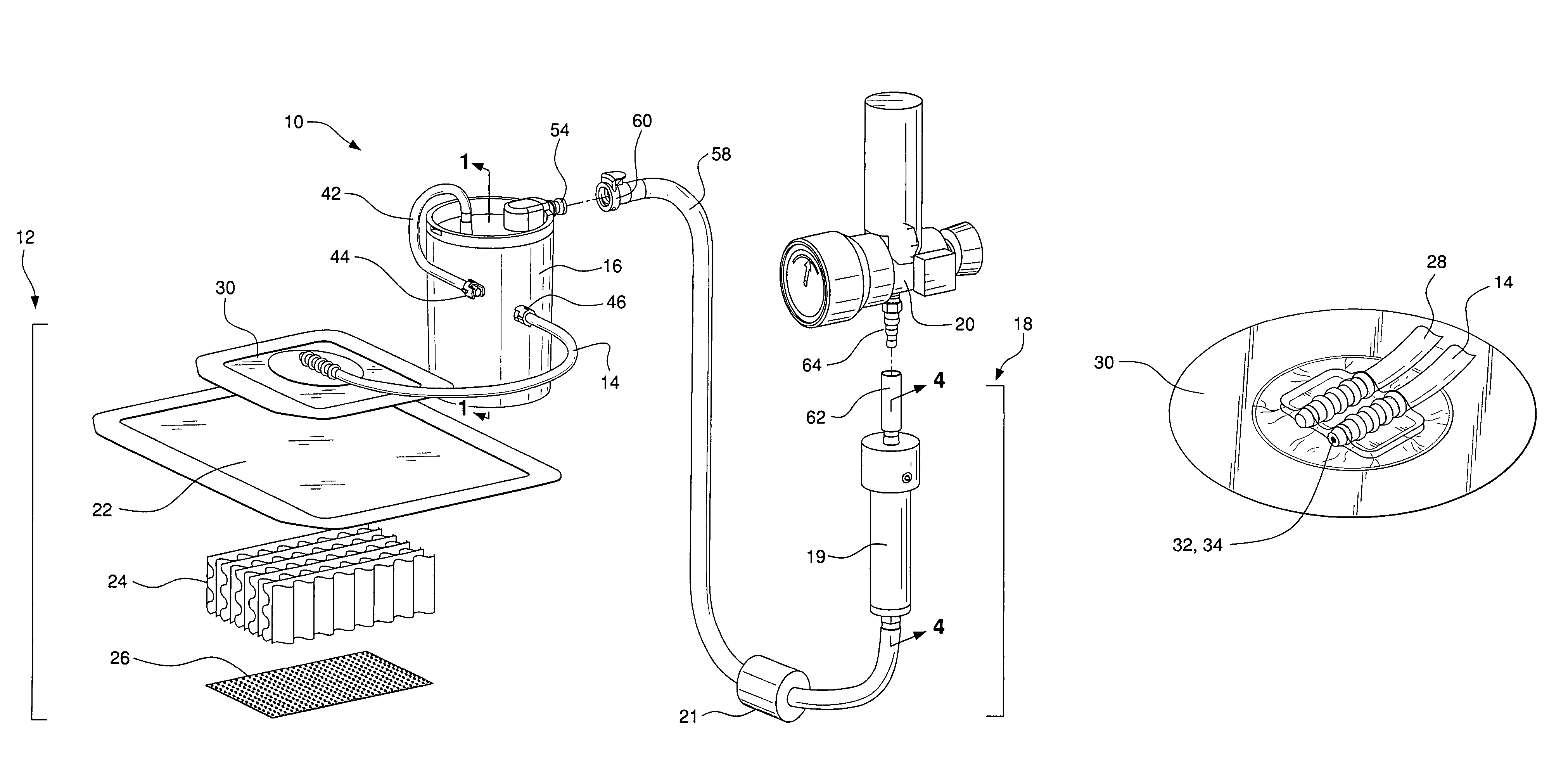
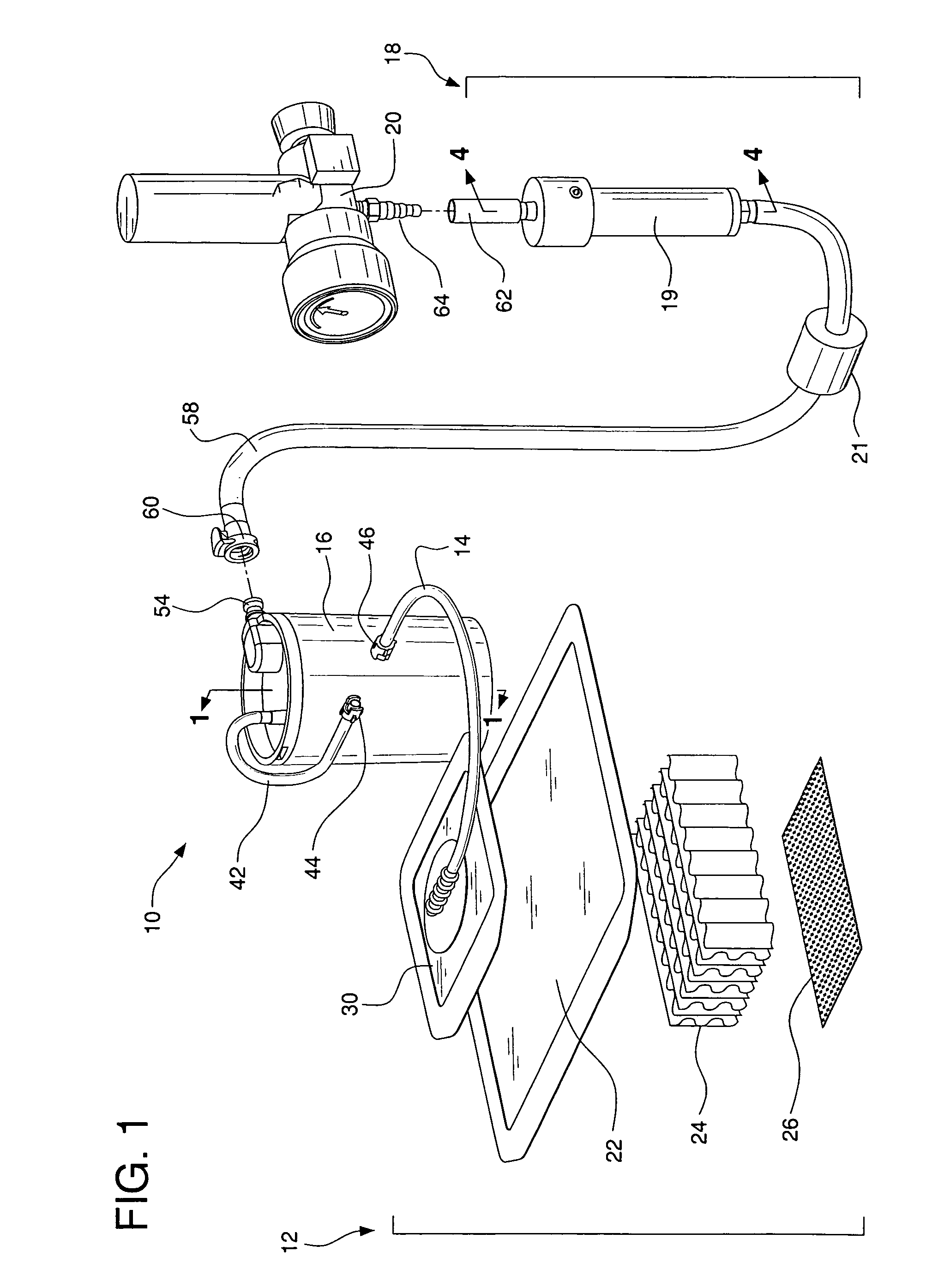
[0025]FIG. 1 shows an embodiment of a system (10) for suction wound therapy. The components include a wound dressing subsystem (12), a suction tube (14), a waste collection canister (16), a flow monitor instrument (18) and a wall suction regulator (20) of a stationary suction source.

The Wound Dressing

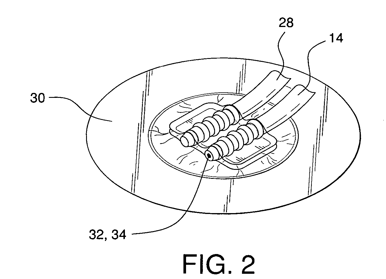
[0026]The typical wound dressing (12) includes a wound cover (22) and wound packing material (24), and may include a special wound contact layer (26). It will have a suction tube (14) running under the edge of the primary cover or through the cover, or will terminate outside of the cover and communicate with a nozzle or slot in the cover. There is a wide variety of each of these components. The wound dressing (12) shown in the drawings and described herein uses presently preferred components, but the invention is not intended to be limited to these components.

[0027]The primary wound cover (22) is preferably an airtight wound cover that is vapor permeable. It is preferred to use a thin f...


PUM


Abstract

A system for applying suction to a wound uses a reference airflow for monitoring system operation. A reference airflow (or “controlled leak”) to the suction source is provided when the system is in operation, such that deviation from the reference airflow can be monitored as an indication of a change in operation, such as a leak in the seal of the wound cover, a blockage of airflow from crimping of the suction conduit or overfill of the waste collector, or an inadvertent turn off or disconnect from the suction source.

Description

REFERENCE TO RELATED APPLICATIONS[0001]This application claims priority of U.S. Provisional Application No. 60 / 699,218, filed Jul. 14, 2005.FIELD OF THE INVENTION[0002]The invention is related to the general field of wound treatment, and to the more specific field of devices for wound drainage and treatment with suction.BACKGROUND OF THE INVENTION[0003]It is well known to treat wounds by applying suction under airtight wound covers. The suction can be used to aspirate wound exudate and other liquids from the wound and / or the wound packing materials, and suction can be applied as a healing modality for its well known antiseptic and tissue regeneration effects.[0004]A primary concern in using suction assisted wound therapy is maintaining suction pressure at the wound. It is increasingly recognized that once suction wound dressings are applied, the suction should be maintained at certain levels. Loss of suction to the wound can result if leaks or blockages occur in the system.[0005]Lea...

Claims


Application Information

Patent Timeline
Patent Type & Authority Patents(United States)
IPC IPC(8): A61M1/00A61B18/18A61F5/44
CPCA61M1/0001A61M1/0031A61M1/0066A61M1/0088A61M1/0092A61M27/00A61M1/0025A61M1/0052A61M1/0086A61M2205/123A61M2205/3331A61M2205/8237A61M2205/15A61M2205/8206A61M1/784A61M1/86A61M1/80A61M1/964A61M1/882A61M1/74A61M1/982A61M1/96A61M1/92A61M1/60A61M1/72A61M1/73
Inventor KARPOWICZ, JOHNRADL, CHRISTOPHER L.KLOCEK, KEVIN P.BOEHRINGER, JOHN R.NORTON, DEREK
Owner PAUL HARTMANN AG
Why Eureka
Try Eureka