Cord type thermal fuse and sheet type thermal fuse

a thermal fuse and thermal insulation technology, applied in the direction of relays, electrical equipment, protective switches, etc., can solve the problems of affecting the reliability of operative operation, and affecting the operation of a long-term use. , to achieve the effect of preventing deterioration of operative reliability, increasing production costs, and preventing inconvenient operation

Inactive Publication Date: 2008-10-21
KURABE IND CO LTD
View PDF33 Cites 7 Cited by
  • Summary
  • Abstract
  • Description
  • Claims
  • Application Information

AI Technical Summary

Benefits of technology

[0018]Accordingly, it is possible to obtain the cord type thermal fuse, which is surely disconnected at abnormal high temperature even at any position to which any compression force is not applied, and after disconnection, which has no risk of re-contact by melted conductor, etc., whereby any inappropriate operation is prevented. Further, it is also possible to obtain the sheet type thermal fuse substantially having the same characteristic as that of the cord type thermal fuse as mentioned above.
[0019]The thermal fuse of the present invention may further serve, not only for prevention of deterioration of operative reliability due to lost of flux function under practical using conditions, but also for improvement of operative reliability of aged cord type thermal fuse, against such as formation of surface oxide film due to thermal oxidization of conductor.
[0020]In addition, the thermal fuse of the present invention is useful, because there is substantially no change of the structure of such a thermal fuse as compared with that of conventional thermal fuses assembly, it is also possible to use widely as a safety device for various heat apparatus, by not increasing the production cost.

Problems solved by technology

There are lead wires connected to the both ends of the conductor via terminals, and when the conductor melts at excessive temperature the electric connection between the lead wires is cut, whereby the abnormal state is detected.
However, according to these types of cord type thermal fuses, since there have been high-integration of structure of combustion apparatus, the thermal ambience during long-term use becomes severer.
Thus, the deterioration of flux would be prompted due to aging by heat, or the reliability of conductor would be lowered by heat, and it should be foreseen that a quick response to temperature would not be obtained after deterioration due to thermal aging.
Thus, when the protection tube is ripped and damaged by edges, etc. of metal parts inside the combustion apparatus, there would be a higher risk of electric leakage by intrusion of water, and also a higher risk of prompted deterioration of flux due to aging by intrusion of exhaust gas.

Method used


Image

  • Cord type thermal fuse and sheet type thermal fuse
  • Cord type thermal fuse and sheet type thermal fuse
  • Cord type thermal fuse and sheet type thermal fuse

Examples


example 1

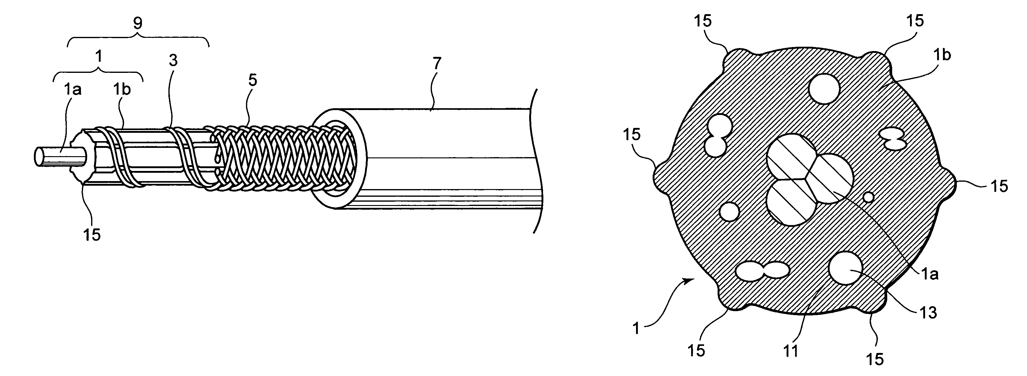
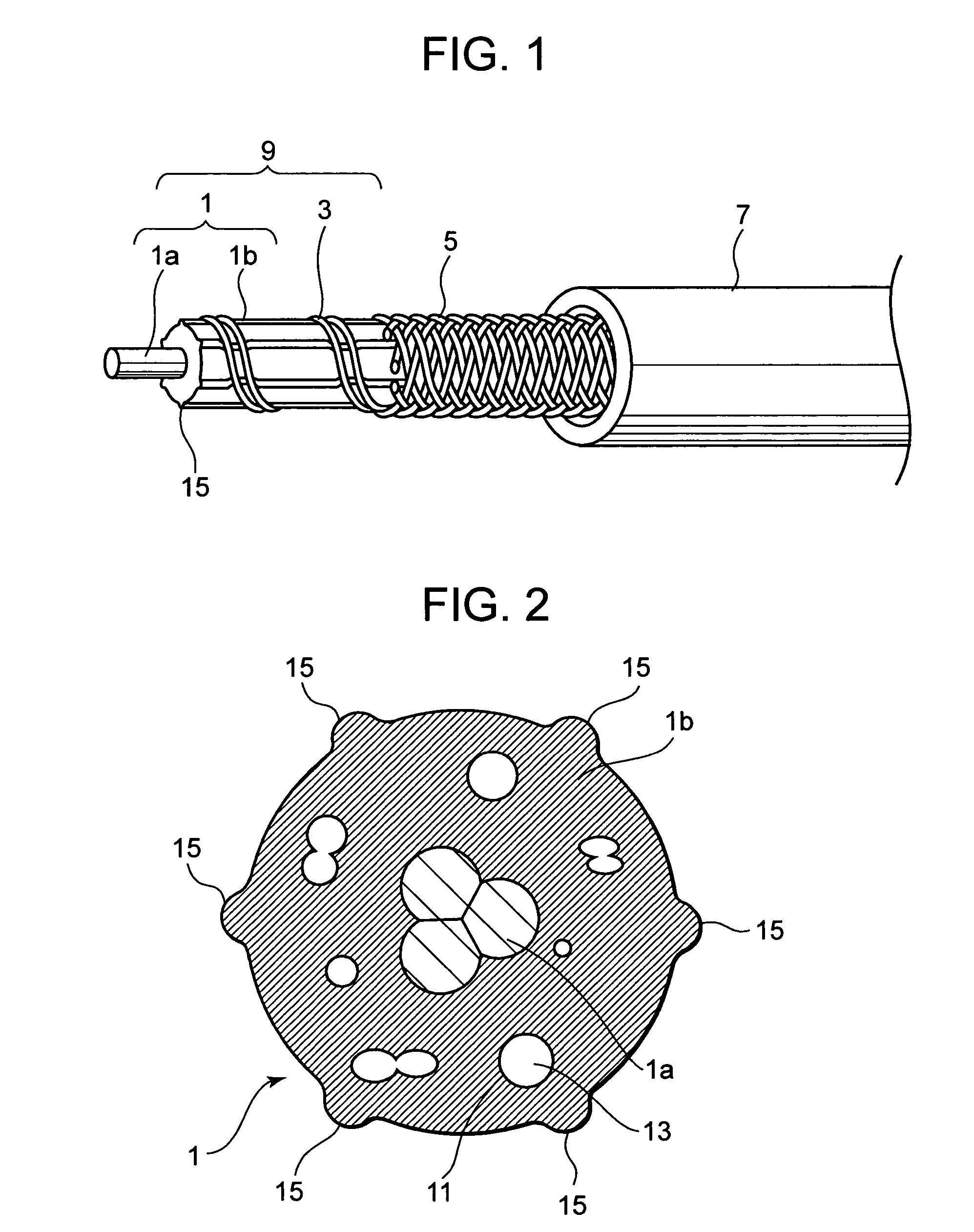
[0053]The elastic core 1 was manufactured by the following methods. First, silicone varnishing was applied to a glass cord having the outer diameter of about 0.7 mm, thus the tensile resistant member 1a was provided. Thereafter, a silicone rubber, comprising a compound of 100 w / t parts (part by weight) of silicone rubber, 1 w / t part of foaming agent (AIBN) and 2 w / t parts of organic peroxide cross-linking agent kneaded on open roll, was extruded in order to cover the periphery of the tensile resistant member 1a, so that the cross-section of the silicone rubber had six radial protrusions, of which inscribed circle was 1.6 mm and of which circumscribed circle was 1.8 mm. At the same time, the silicone rubber was foamed by applying hot-air vulcanization. Thus, the foamed elastic member 1b, having isolated air holes, was formed.

[0054]Thereafter, two parallel conductors 3, respectively comprising 0.6 mm of eutectic solder wire (melting temperature at 183° C.) in which flux had been inclu...

experiment 1

Initial Operative Temperature

Experiment Method:

[0057]The cord type thermal fuse assembly manufactured by the above method was inserted in a glass fiber braid tube at inner diameter of 4.0 mm and at length of about 15 cm, so that the cord type thermal fuse part of the assembly may come to the center part of the tube. Thereafter, an electric current about 0.1 A was applied from 100 V AC power supply, by connecting incandescent bulb to the both terminals of the lead wires as an outer load. Then, the center part was heated from normal temperature, at temperature increase speed of 10° C. / min. Thus, when the conductor 3 was disconnected, the temperature was checked.

experiment 2

Operative Temperature After Lost of Flux

Experiment Method:

[0058]The manufactured cord type thermal fuse assembly was placed in a hot-air circulation type of constant-temperature bath at temperature of 158° C., for 384 hours, whereby the deterioration due to aging by heat was prompted, and the flux was decomposed and removed by heat. Thereafter, the cord type thermal fuse assembly after heat treatment was inserted in a glass fiber braid tube at inner diameter of 4.0 mm and at length of about 15 cm, so that the cord type thermal fuse part of the assembly may come to the center part of the tube. Thereafter, an electric current about 0.1 A was applied from 100 V AC power supply, by connecting incandescent bulb to the both terminals of the lead wires as an outer load. Then, the center part was heated from initial temperature of 250° C., at temperature increase speed of 10° C. / min. Thus, when the conductor 3 was disconnected, the temperature was checked.

[0059]The results of Experiments 1 ...


PUM


Abstract

A cord type thermal fuse, comprising a fuse core produced by winding a conductor meltable at a predetermined temperature on an insulating core member continuous in the length direction, and an insulating cover covering the outer periphery of the fuse core, wherein the conductor can be cut by expanding the insulating core member at a predetermined temperature and / or by contracting the insulating cover at the predetermined temperature.

Description

TECHNICAL FIELD[0001]The present invention relates to a cord type thermal fuse and a sheet type thermal fuse, which can be disconnected when any part thereof is exposed in an abnormal high temperature state, so that the abnormal temperature can be detected. More particularly, the present invention relates to the cord type thermal fuse and the sheet type thermal fuse, of which disconnection time is still good even after being deteriorated due to aging by heat, and which has good operative reliability.BACKGROUND ART[0002]For example, according to Japanese Unexamined Patent Publication No. Hei 6-181028, there has been disclosed a cord type thermal fuse, comprising a space layer and an insulating cover layer around a center core member, on which a conductor meltable at a predetermined temperature is wound in the lateral direction on an elastic core. There are lead wires connected to the both ends of the conductor via terminals, and when the conductor melts at excessive temperature the e...

Claims


Application Information

Patent Timeline
Patent Type & Authority Patents(United States)
IPC IPC(8): H01H85/04H01H85/10H01H85/20H01H37/74
CPCH01H37/74
Inventor HASE, YASUHIRONOZUE, HIROSHI
Owner KURABE IND CO LTD
Why Eureka
Try Eureka