Thermal isolation devices and methods for heat sensitive downhole components

a technology of heat-sensitive components and thermal isolation devices, which is applied in the direction of insulation, borehole/well accessories, survey, etc., can solve the problems of affecting the use of instruments, affecting the efficiency of the operation of the equipment, and affecting the efficiency of the equipment. , to achieve the effect of reducing the cross-sectional area, and preventing the flow of hea

Inactive Publication Date: 2008-10-21
BAKER HUGHES INC
View PDF10 Cites 77 Cited by
  • Summary
  • Abstract
  • Description
  • Claims
  • Application Information

AI Technical Summary

Benefits of technology

[0007]In aspects, the present disclosure provides devices for isolating one or more heat sensitive components deployed in a downhole environment. In one arrangement, the device includes a heat sink positioned adjacent to a heat sensitive component. The heat sink is configured to have a stepped thermal response to an applied heat. In one embodiment, the heat sink includes two masses that are substantially thermally decoupled. The thermal decoupling may be achieved by positioning a nanoporous material between the two masses. The heat sink may also have more than two masses so arranged. The heat sensitive component and the heat sink may be positioned in an interior of a container that is configured to be deployed into a wellbore with a conveyance device. The container may be a Dewar-like flask. A connector may be used to connect the heat sink to the container. The connector operates as a thermal isolator that impedes the flow of heat into the interior of the container. The connector may be formed of stainless steel, titanium or other material having a low thermal conductivity. In one embodiment, the connector includes at least one bridge portion having a reduced cross-sectional area that impedes the flow of heat. In some arrangements, the connector may include one or more elongated openings aligned along a longitudinal axis of the connector. These openings also reduce the cross-sectional area through which heat can flow. In certain embodiments, a nanoporous material may be positioned in the container at locations that assist in thermally isolating the heat sink or other components from a heat applied by the downhole environment.
[0008]In aspects, one method provided by the present disclosure includes conveying a downhole tool into a wellbore using a conveyance device such as a wireline, a slickline, a coiled tubing, or drill pipe. To thermally isolate heat sensitive components associated with the downhole tool, the heat sensitive components may be positioned in the interior of a container coupled to the conveyance device. The heat sensitive components may be used in connection with downhole processing devices, sensors, transmitters, memory devices, communication devices, electronic devices, etc. During deployment downhole, the container provides one thermal barrier for these heat sensitive components. A connector connects the components inside the container to the container. The low thermal conductivity of the connector along with reduced cross-sectional areas also forms a thermal barrier against heat applied by the downhole environment. Within the container, a heat sink positioned adjacent to the heat sensitive component absorbs heat that does enter the container interior that would otherwise detrimentally affect the heat sensitive components. As described earlier, the heat sink may be configured to have a stepped thermal response to an applied heat and may absorb heat applied by the downhole environment as well as heat generated by components inside the container.
[0009]It should be understood that examples of the more important features of the invention have been summarized rather broadly in order that detailed description thereof that follows may be better understood, and in order that the contributions to the art may be appreciated. There are, of course, additional features of the invention that will be described hereinafter and which will form the subject of the claims appended hereto.

Problems solved by technology

Temperature and pressure conditions such as these can have an adverse effect on instruments used downhole.
Heat especially can be undesirable for tools having electronic components.
Generally speaking, exposure to excess heat can cause electronic components to work improperly or even fail.

Method used


Image

  • Thermal isolation devices and methods for heat sensitive downhole components
  • Thermal isolation devices and methods for heat sensitive downhole components
  • Thermal isolation devices and methods for heat sensitive downhole components

Examples


Embodiment Construction

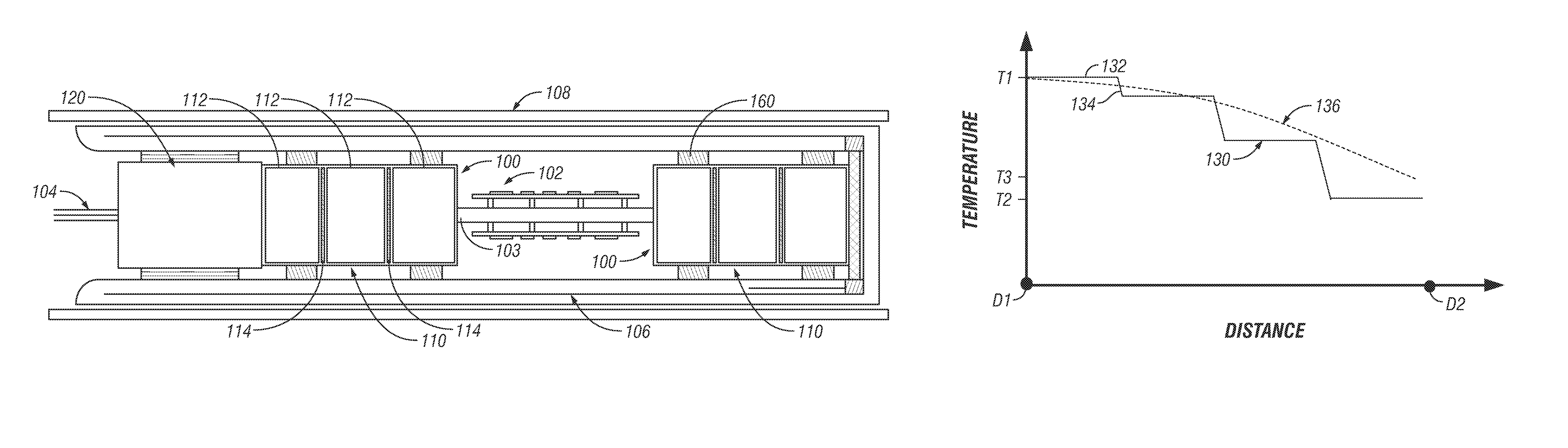
[0017]The present disclosure relates to devices and methods isolating heat sensitive components from a wellbore environment and / or heat generated by downhole components. The term “heat sensitive component” shall hereinafter be used to refer to any tool, electrical component, sensor, electronic instrument, structure, or material that degrades either in performance or in integrity when exposed to temperatures above 200 degrees centigrade. For purposes of discussion, a wellbore may be considered “hot” if the ambient temperature compromises or impairs the structural integrity, operating efficient, operating life, or reliability of a given tool, device, or instrument.

[0018]Aspects of the present disclosure may be utilized to increase temperature survival time of downhole tools and thereby increase the time heat sensitive equipment may be deployed in a wellbore. As will be appreciated, the present invention is susceptible to embodiments of different forms. There are shown in the drawings,...


PUM


Abstract

A device for isolating a heat sensitive component includes a heat sink positioned adjacent to the heat sensitive component. The heat sink has a stepped thermal response to an applied heat. The heat sink may include two or more thermally decoupled masses. Thermal decoupling may be achieved by positioning a nanoporous material positioned between the two masses. The heat sensitive component and the heat sink may be positioned inside a container such as a Dewar-like flask and connected to the container with a connector. The connector may function as a thermal isolator that impedes the flow of heat into the interior of the container. In one embodiment, the connector includes at least one bridge portion having a reduced cross-sectional area and/or a longitudinally elongated opening to impede heat flow. Nanoporous material may be positioned in the container at locations that assist in thermally isolating the heat sink and heat sensitive components.

Description

BACKGROUND OF THE DISCLOSURE[0001]1. Field of the Invention[0002]The disclosure relates to protecting and / or isolating heat sensitive components used in downhole applications.[0003]2. Description of the Prior Art[0004]Oil and gas are generally recovered from subterranean geological formations by means of oil wells. For the purposes of this disclosure, an oil well is a hole drilled through the Earth above such geological formations. Typically, the well is drilled to and more often through an oil producing formation. This hole is commonly referred to as a wellbore or bore hole of the oil well and any point within the wellbore is generally referred to as being downhole.[0005]Wellbore temperatures can vary from ambient up to about 500° F. (260° C.) and pressures from atmospheric up to about 30,000 psi (206.8 mega pascals). Temperature and pressure conditions such as these can have an adverse effect on instruments used downhole. Heat especially can be undesirable for tools having electro...

Claims


Application Information

Patent Timeline
Patent Type & Authority Patents(United States)
IPC IPC(8): H05K7/20E21B36/00
CPCE21B47/011E21B47/017E21B47/0175
Inventor RAFIE, SAEED
Owner BAKER HUGHES INC
Why Eureka
Try Eureka