Transfer tray for surgical sharps

a technology for transferring trays and surgical instruments, applied in the directions of transportation and packaging, application, incision instruments, etc., can solve the problem that the scalpel cannot be placed in the scalpel slo

Active Publication Date: 2008-10-28
HOFTMAN MIKE
View PDF9 Cites 95 Cited by
  • Summary
  • Abstract
  • Description
  • Claims
  • Application Information

AI Technical Summary

Benefits of technology

[0007]The present invention is a dual function transfer tray that can be used for either a scalpel or a suturing needle holder with suturing needle. A scalpel slot is formed in the bottom of a relatively deep set of sloped walls. A half-cylindrical suture needle cavity is formed above the first slot. However, at a mid-section of the scalpel slot and the half-cylindrical suture needle cavity are opposing and deep V-shaped cutaway sections in the sidewalls with a flat floor section between them. A user need never have to focus their attention for more than a split second to discern the location of the mid-section of the transfer tray. The user's thumb and forefinger are aimed at the V-shaped sidewall openings to grasp a midsection of a supported surgical sharps. The scalpel slot and half-cylindrical suture needle cavity are set relatively deep with respect to top edges of the transfer tray to form an open tray to prevent a user from being inadvertently injured by a scalpel blade or a suture needle. In addition, the scalpel cannot be placed in the scalpel slot unless it rests on one of its longitudinal edges, preferably the same one as that of its blade edge. Thus, a user grasping the mid-section of the scalpel handle in the cutaway and flat floor section picks up the scalpel in a ready-to-use position.
[0009]Thus, a needle holder's own weight urges it down the handle surfaces of one end of the transfer tray toward an end wall at the other end of the transfer tray. The suturing needle is in this manner urged toward the end wall and is protectively supported within the half-cylindrical suture needle cavity. The jaws-end of the needle holder stops downward sliding of the needle holder.
[0011]The sharps piece after use can be very easily replaced in the transfer tray to be easily accessible for re-use during surgical procedures.
[0012]In a particularly important advantage, a surgeon need not even look at the transfer tray to safely pick up a scalpel or needle holder from the invention transfer tray. The cutaway portions of the long sidewalls are so dramatically different in elevation than the other top edges of the tray that a user can tell where to direct their thumb and fingers by simple detection of the cutaway sections by touch. A user knowing generally where the tray is located can place their palm and fingers in that area and quickly by touch detect the broad cutaway parts of the mid-section of the tray. The user can direct their thumb and forefingers to the opposite sides of the cutaway parts and instantly close in on the desired sharps piece. In the instant invention, a sharps piece may also be a pair of scissors or other ring-handled instrument with a sharp or cutting end.
[0015]In another embodiment, at least one long side of a rectangular form of the invention tray is laterally extended to provide a platform in which are defined connector slots and connector pins. Two of the invention connector trays may be quickly and releaseably connected. One tray bears two connector pins and the other tray bears two connector slots. The connector pins on one tray are inserted in the connector slots of another tray and one tray is moved so that the connector pins lock into a secure position in the connector slots of the other tray. Two or more invention trays can be securely locked together side by side so that multiple surgical sharps can be offered to a surgeon without the need to fumble for a second tray.
[0017]The present invention tray improves the user's ability to recover a previously used surgical sharp piece. The surfaces in the invention tray are downward contoured at relatively steep angles so that when a surgical sharp is dropped on the tray with little care to align the piece to the tray, the piece will quickly slide down the concavity walls to be aligned into the protected overall concavity of the tray.

Problems solved by technology

In addition, the scalpel cannot be placed in the scalpel slot unless it rests on one of its longitudinal edges, preferably the same one as that of its blade edge.

Method used


Image

  • Transfer tray for surgical sharps
  • Transfer tray for surgical sharps
  • Transfer tray for surgical sharps

Examples


Embodiment Construction

[0034]The invention is now discussed with reference to the figures.

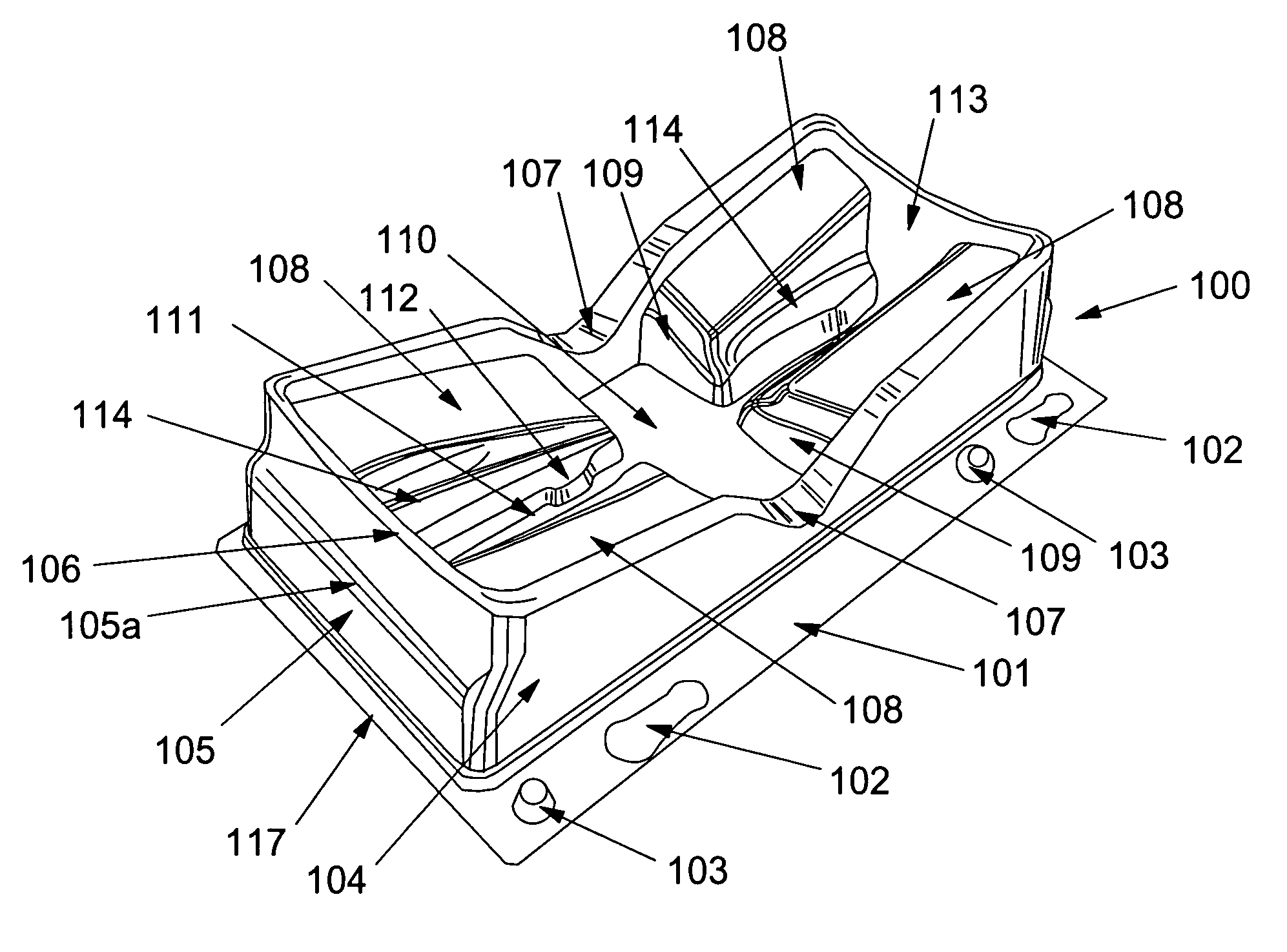
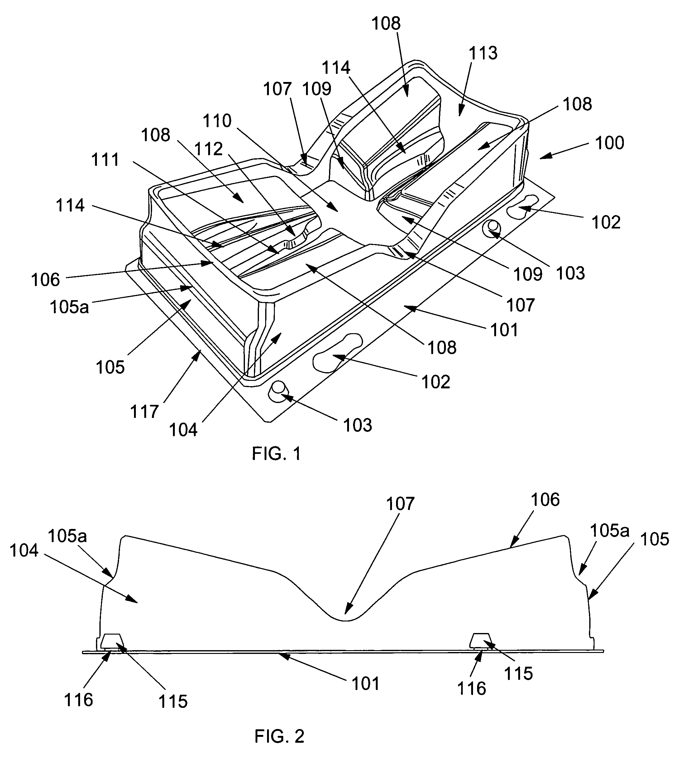
[0035]FIG. 1 shows tray 100 comprising a rigid plastic shell formed by injection molding or vacuum forming. Tray 100 has significant concavities on the top and bottom sides. The concavities on the top side are adapted to securely support surgical sharps as defined above.

[0036]Tray 100 comprises a bottom edge rim 117 on three sides and rim 101 on a long side of the rectangular shape of the tray. The rims 101 and 117 support the tray 100 when it is placed on a flat surface such as a tabletop. Rim 101 is sufficiently wide so that it accommodates lug slots 102 and lugs 103. As shown in FIGS. 2 and 6, lugs 103 comprise a top part 115 and neck part 116. To securely join two adjacent trays 100 in a side by side arrangement (as shown in FIG. 12), lugs 103U of the upper tray 100U are inserted into the lug slots 102L of lower tray 100L and tray 100U is moved longitudinally to the left in lug slots 102L until the neck parts 116...


PUM


Abstract

The present invention is a dual function transfer tray that can be used for either a scalpel or a suturing needle holder with suturing needle. A scalpel slot is formed in the bottom of a relatively deep set of sloped walls. A suture needle cavity is formed above the first slot. However, at a mid-section of the scalpel slot and the half-cylindrical suture needle cavity are opposing and deep V-shaped cutaway sections in the sidewalls with a flat floor section between them. A user need never have to focus their attention for more than a split second to discern the location of the mid-section of the transfer tray. The user's thumb and forefinger are aimed at the V-shaped sidewall openings to grasp a midsection of a supported surgical sharps. The scalpel slot and half-cylindrical suture needle cavity are set relatively deep with respect to top edges of the transfer tray and the to form an open tray to prevent a user from being inadvertently injured by a scalpel blade or a suture needle. In addition, the scalpel cannot be placed in the scalpel slot unless it rests on one of its longitudinal edges, preferably the same one as that of its blade edge. Thus, a user grasping the mid-section of the scalpel handle in the cutaway and flat floor section picks up the scalpel in a ready-to-use position.

Description

BACKGROUND OF THE INVENTION[0001]The present invention relates to transfer trays for surgical sharps, especially those having a concavity for securing said sharps.[0002]In surgical procedures, surgical sharps are passed between operating room personnel. The most important of these transfers is the one delivering the sharps piece to the operating surgeon. The surgeon's intense attention is focused on the portion of the patient's body to be addressed by the surgeon. Passage of surgical sharps to a necessarily distracted surgeon has in the past resulted in puncture or cutting wounds to the surgeon as he or she reaches for a surgical sharp piece.[0003]In an attempt to reduce the likelihood of surgeon injury during passage of surgical sharps, one prior art device comprises an open topped kidney shaped dish fitted with slightly elevated ribs at the dish bottom. The surgical sharp piece is simply placed in the dish concavity so that the piece is supported by parallel ribs. A slight tilt of...

Claims


Application Information

Patent Timeline
Patent Type & Authority Patents(United States)
IPC IPC(8): B65D85/28
CPCA61B19/0256A61B19/0271A61B17/06114A61B17/062A61B17/3215A61B50/33A61B50/20
Inventor HOFTMAN, MIKE
Owner HOFTMAN MIKE
Why Eureka
Try Eureka