
Process for the removal of volatile compounds from mixtures of substances using a micro-evaporator

a technology of micro-evaporator and mixture, which is applied in the direction of indirect heat exchanger, lighting and heating apparatus, bacteria antigen ingredients, etc., can solve the problems of long residence time, unfavorable mass and heat transfer, and often overheating of products

Inactive Publication Date: 2008-10-28
BAYER MATERIALSCIENCE AG
View PDF6 Cites 38 Cited by
  • Summary
  • Abstract
  • Description
  • Claims
  • Application Information

AI Technical Summary

Benefits of technology

The present invention is about a way to remove a certain chemical from a mixture of other substances using a small device called a micro-evaporator. This device has tiny channels that can carry the mixture of substances and has a specific surface area of at least 103 m2 / m3. The process helps to remove the volatile compound from the mixture.

Problems solved by technology

In helical coil-type evaporators the product is often overheated, especially if the evaporator is operated with a pressure maintained at the outlet.
In falling-film or centrifugal evaporators, relatively large film thicknesses of up to 1 mm and up to 0.1 mm respectively are achieved, which have an unfavourable influence on mass and heat transfer and thus require a longer residence time.

Method used


Image

  • Process for the removal of volatile compounds from mixtures of substances using a micro-evaporator
  • Process for the removal of volatile compounds from mixtures of substances using a micro-evaporator

Examples


example 1

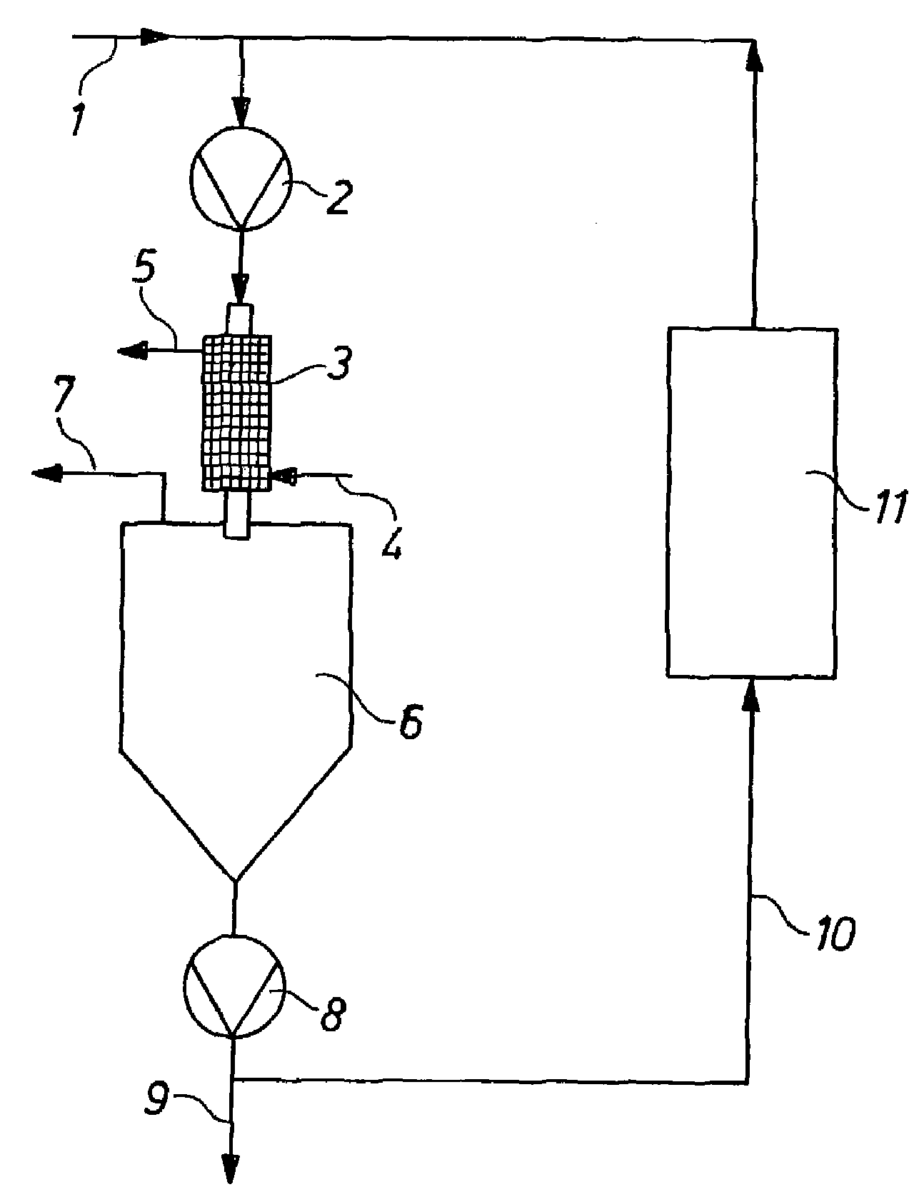
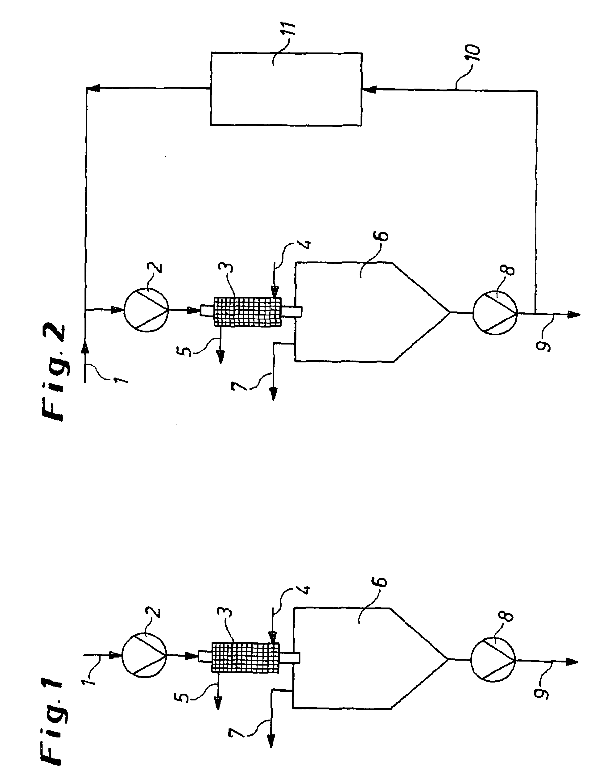
[0038]The crude product was supplied at a temperature of 60° C. and a feed rate of 60 kg / h to the microstructured evaporator 3 heated with 30 bar steam (230° C.) and having a deflecting separator 6 connected in series. The microstructured evaporator 3 had the following channel dimensions: length×width×height: 40 mm×200 μm×100 μm. The hydraulic diameter was 133 μm. The heat transfer surface area was 0.135 m2, the specific evaporator surface area 2·104 m2 / m3. The residence time in the microstructured evaporator 3 was approximately 0.3 s. 21 kg / h of distillate (Desmodur W®) were separated off in this stage through the deflecting separator 6 under a pressure of 0.8 mbar. The crude product concentrated in this way to a Desmodur W® content of 7.8 wt. % was then transferred to a film evaporator (evaporator surface area 1 m2) heated to 230° C., which was operated under a pressure of 0.5 mbar. At the outlet from the film evaporator a polyisocyanate resin was obtained with an NCO content of 2...

example 2

Comparative Example

[0039]The crude product was supplied at a temperature of 60° C. through a line concurrently heated with 6 bar steam (160° C.) at a feed rate of 30 kg / h to a falling-film evaporator with a deflecting separator connected in series. The heat transfer surface area was 0.314 m2, the specific evaporator surface area was 1.57·102 m2 / m3. Evaporator and separator were heated with 30 bar steam to 230° C. Distillation took place under 0.8 mbar. A distillate quantity of 9 kg / h Desmodur W® was obtained in this stage.

[0040]As in Example 1, the crude product concentrated in this way to a Desmodur W® content of 14.4 wt. % was then transferred to a film evaporator (evaporator surface area 1 m2) heated to 230° C., which was operated under a pressure of 0.5 mbar. At the outlet from the film evaporator a polyisocyanate resin was obtained with an NCO content of 2.90 wt. %, which contained a residual content of 1.25 wt. % of the Desmodur W® that was used.

[0041]The comparison between ex...


PUM

PropertyMeasurementUnit
hydraulic diameteraaaaaaaaaa
temperatureaaaaaaaaaa

Abstract

A process for the removal of at least one volatile compound from a reactive or unreactive mixture of substances with the aid of at least one micro-evaporator, the micro-evaporator displaying channels for carrying the mixture of substances having a hydraulic diameter of 5 to 1000 μm and a specific evaporator surface area of at least 103 m2 / m3.

Description

CROSS REFERENCE TO RELATED PATENT APPLICATION[0001]The present patent application claims the right of priority under 35 U.S.C. § 119 (a)-(d) of German Patent Application No. 103 35 451.4, filed Aug. 2, 2003.BACKGROUND OF THE INVENTION[0002]1. Field of the Invention[0003]The invention concerns a process for the removal of volatile compounds from reactive or unreactive mixtures of substances.[0004]2. Description of the Prior Art[0005]Film evaporators are conventionally used in industry for evaporating volatile substances from unreactive, heat-sensitive mixtures of substances. Examples include helical coil-type evaporators, falling-film evaporators and centrifugal evaporators. In helical coil-type evaporators the product is often overheated, especially if the evaporator is operated with a pressure maintained at the outlet. In falling-film or centrifugal evaporators, relatively large film thicknesses of up to 1 mm and up to 0.1 mm respectively are achieved, which have an unfavourable in...

Claims


Application Information

Patent Timeline
Patent Type & Authority Patents(United States)
IPC IPC(8): B01D1/30B01J19/00F28D15/00B01D1/00B01D53/00
CPCB01D1/00B01D53/00C08F6/003F28F2260/02Y10S165/911
Inventor KUPPER, KURT-MANFREDWILMES, OSWALDSTEENBECK, HARTMUTNAGEL, ALMUT
Owner BAYER MATERIALSCIENCE AG
Learn More