Impact resistant roofing shingles and process of making same

a technology of impact resistance and roofing shingles, which is applied in the direction of chemistry apparatus and processes, weaving, synthetic resin layered products, etc., can solve the problems of increasing the cost of asphalt coating raw materials, not being very effective in resisting, and plain and rocky mountain states are particularly susceptible to roofing damage, etc., to achieve simple design and manufacture, and minimal cost increase

Active Publication Date: 2008-10-28
BMIC LLC
View PDF8 Cites 42 Cited by
  • Summary
  • Abstract
  • Description
  • Claims
  • Application Information

AI Technical Summary

Benefits of technology

[0011]A new roofing material has now been discovered which, although simple in design and ease of manufacture, and at minimal increase in cost over standard roofing shingles, produces improved results that meet the most stringent requirements imposed by state agencies for impact resistant roofing materials in the United States.
[0012]Although the invention is independent of any theory explaining its effectiveness, it is believed that the utilization of a laminate structure provides two means of protecting a roofing shingle from impact damage. First, the laminate structure may protect the shingle from cracks caused by impact and / or the laminate structure may prevent any crack that does develop from propagating due to its cold flow characteristics. That is, if the temperature of the laminate layer is below that of the covering asphalt, the layer is theorized to provide both protection against cracking as well as self sealing protection. If the laminate layer is a material whose melting or decomposition temperature is greater that the covering asphalt the covering is theorized to provide covering protection.

Problems solved by technology

Specifically, such areas as the Plain and Rocky Mountain states are particularly subject to roofing damage caused by hailstorms and the like.
Such designs, although effective in theory, have not been very effective in resisting climatic impacts caused by hailstones and the like.
On the other hand, modifying the asphalt with polymer-type additives increases the asphalt coating raw material cost.
In addition, installation of modified asphalt is more difficult than standard unmodified asphalt coated roofing materials.

Method used


Image

  • Impact resistant roofing shingles and process of making same
  • Impact resistant roofing shingles and process of making same
  • Impact resistant roofing shingles and process of making same

Examples


first embodiment

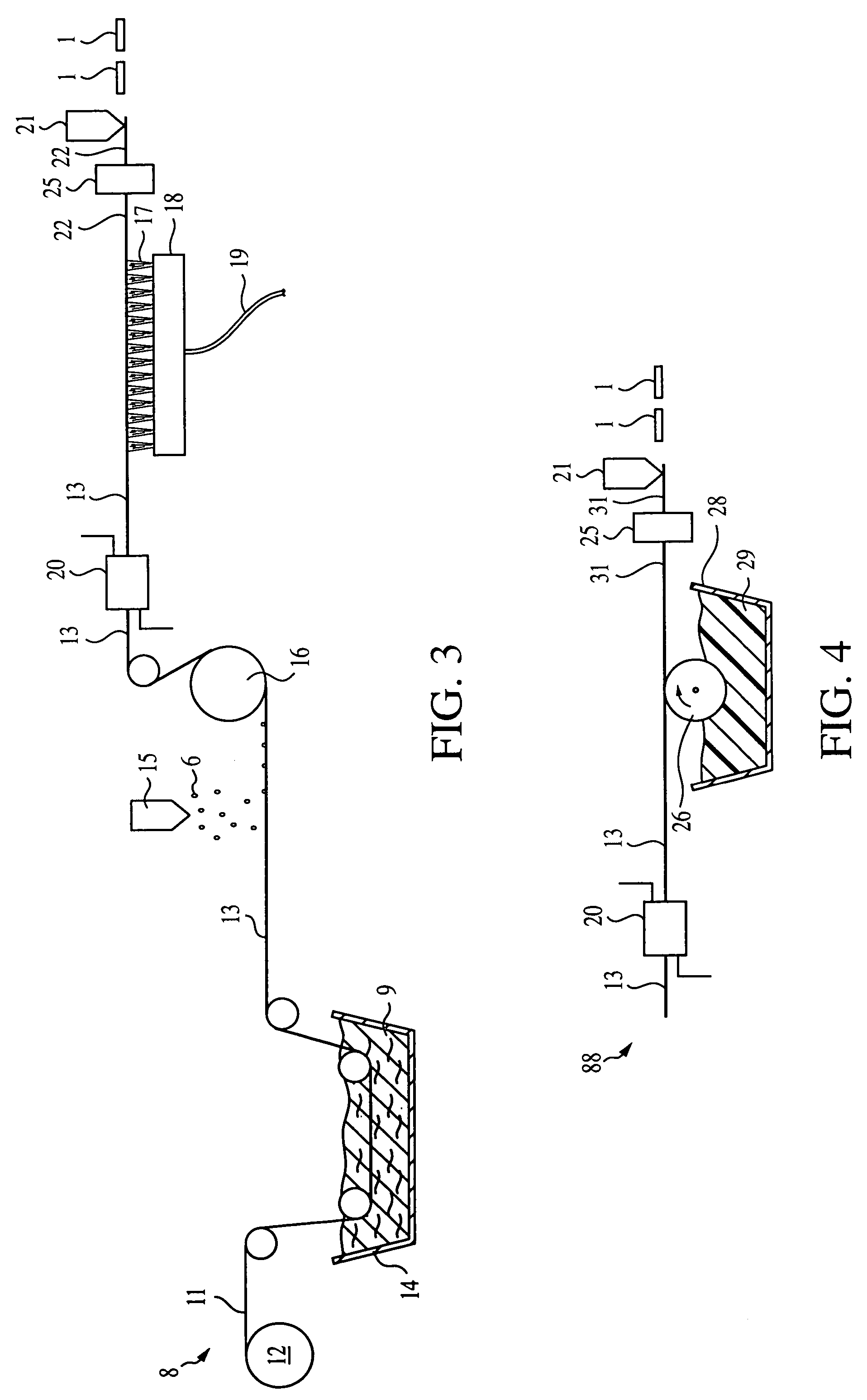
[0031]the process of preparing an impact resistant roofing shingle of the type illustrated by roofing shingle 1 is depicted by apparatus 8. Apparatus 8 includes a roll 12 from which a continuous sheet 11 is payed out. The substrate sheet 11 is passed through a coater 14 filled with asphalt 9. The substrate sheet 11 is thus immersed in the asphalt to completely coat the substrate sheet 11 with a tacky asphalt coating. Although the preferred method of asphalt coating is depicted in apparatus 8, it should be appreciated that other methods, such as by roll application, by spray application, extrusion coating and the like may be employed.

[0032]Insofar as the substrate web 11 downstream of the asphalt coating step is an asphalt coated substrate web, it is identified as web 13. Web 13, coated with tacky asphalt, is, in the preferred embodiment wherein roofing shingle 1 includes granules on its top surface, next passed under a granule dispenser 15 where granules 6 are released onto the top ...

second embodiment

[0039]This second embodiment of roofing shingles 1 is prepared in a process utilizing apparatus 88. Apparatus 88 is identical to apparatus 8 upstream of the downstream end of drying station 20. However, in apparatus 88 the bottom side of dried asphalt coated web 13, downstream of drying station 20, is contacted by a coating roll 26. Coated roll 26 is in communication with modified asphalt 29 disposed in container 28. The bottom side of web 13 is roll coated with a layer of modified asphalt, denoted, downstream of the coating step, as web 31. The processing steps subsequent to modified asphalt coating include drying the modified asphalt coated web 31 a drying station 25 followed by cutting of web 31 into shingles 1. Drying station 25 is the same type of apparatus as is drying station 20.

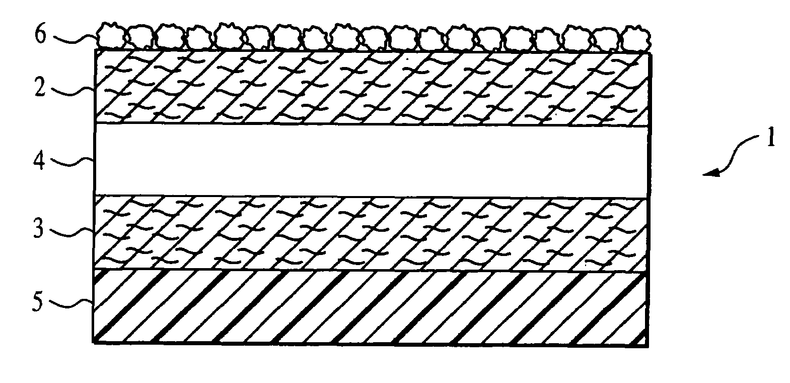
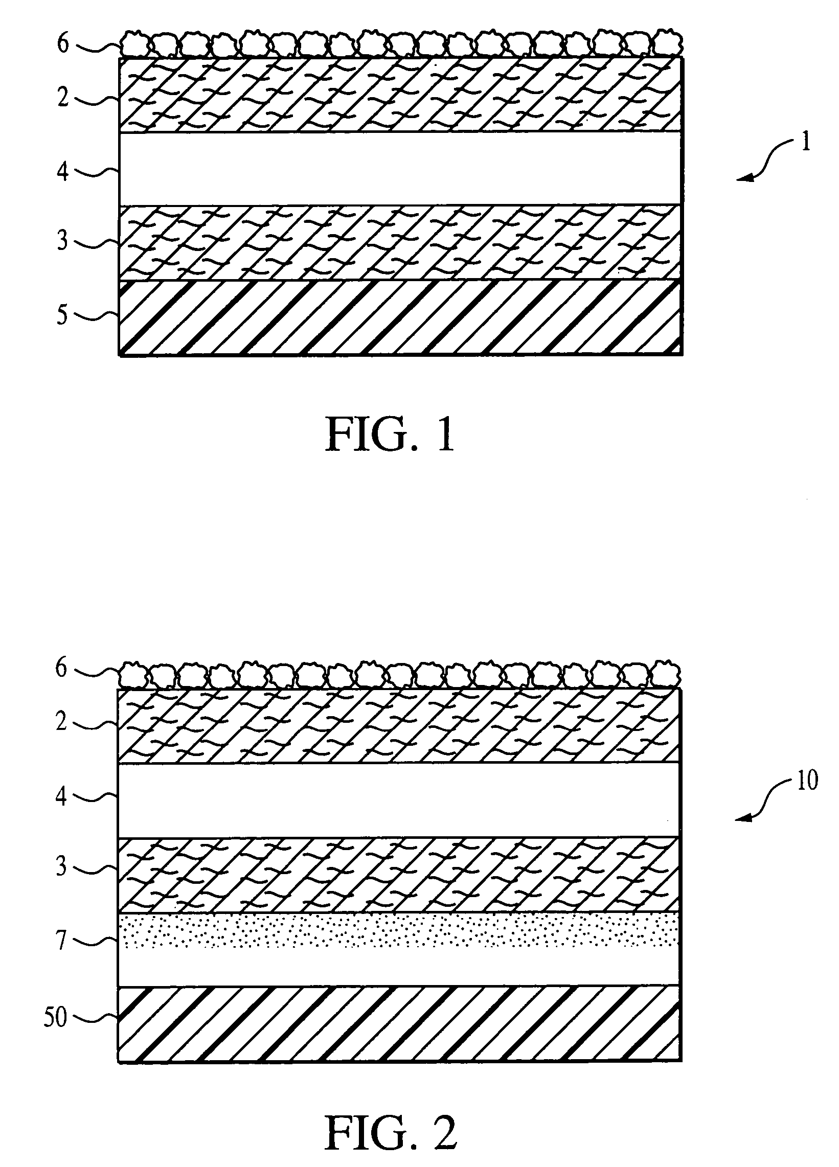
[0040]It is noted that the depiction of impact resistant roofing shingle 1 in FIG. 1 illustrates the layer at the bottom of the asphalt coated substrate to be a plastic, whereas asphalt coatings 2 and...

third embodiment

[0044]The product of this third embodiment is, like the first two embodiments, an impact resistant roofing shingle 1. This is so insofar as the organic film layer 5 of the generic shingle 1 is provided, in this embodiment, by the plastic film of web 32. That is, there is no adhesive bonding the asphalt coating 3 to the plastic film of web 32. The adhesive, bonding the asphalt coating 3 to the plastic film of web 32, is the asphalt coating 3 itself. This is so since the plastic film of web 32 has a melting point, in the embodiment wherein the plastic film is a thermoplastic, or a decomposition temperature, in the embodiment where in the plastic film is a thermosetting resin, higher than the melting temperature of the asphalt coating. The natural tackiness of the asphalt, when compressed with the plastic film web 32 at nip rolls 34, causes the asphalt coating to act as an adhesive.

[0045]Although any plastic film having a melting or decomposition temperature higher than the melting poi...


PUM

PropertyMeasurementUnit
melting temperatureaaaaaaaaaa
impact resistanceaaaaaaaaaa
melting temperaturesaaaaaaaaaa

Abstract

An impact resistant roofing shingle which includes an asphalt coated substrate whose unexposed surface is laminated to an organic film. A process of forming that shingle includes the step of applying an organic film, by spraying a latex, by applying a rubber polymer modified asphalt, by compressing a plastic film having a higher melting or decomposition temperature than the melting point of the asphalt coating or by applying an adhesive to which a plastic film is applied to the unexposed surface of the asphalt coated substrate.

Description

BACKGROUND OF THE DISCLOSURE[0001]1. Field of the Invention[0002]The present invention is directed to an impact resistant roofing shingle providing far greater resistance to impact than standard roofing shingles and a process of making same. More specifically, the present invention is directed to an impact resistant roofing shingle providing the highest level of protection against impact damage to roofing shingles and a process of making those shingles.[0003]2. Background of the Prior Art[0004]Losses sustained to building roofs caused by climatic conditions such as hailstones has focused development of roofing shingles having increased impact resistance. This need in the art is particularly acute in those geographic areas which are subject to these climatic conditions. Specifically, such areas as the Plain and Rocky Mountain states are particularly subject to roofing damage caused by hailstorms and the like. Indeed, the insurance laws of the state of Texas provide cash rebates to ho...

Claims


Application Information

Patent Timeline
Patent Type & Authority Patents(United States)
IPC IPC(8): B32B17/04B32B27/04B32B27/12B32B27/20B32B11/02B32B11/10B32B17/02B32B27/06B32B27/34B32B27/36B32B37/08B32B37/12B32B37/24D06N5/00E04D1/20
CPCB32B11/02B32B17/02B32B27/06B32B27/34B32B27/36B32B37/24D06N5/00E04D1/20B32B11/10Y10T156/1084B32B37/08B32B37/1284B32B38/164B32B2037/243B32B2307/558B32B2395/00E04D2001/005Y10T156/108Y10T156/1052Y10T156/1057Y10T156/1056Y10T442/2615Y10T442/181Y10T442/133Y10T442/674Y10T442/198Y10T442/191Y10T442/2992Y10T442/2123Y10T442/679Y10T442/675Y10T442/167Y10T442/678Y10T442/164Y10T442/676Y10T442/172Y10T442/169B32B2419/06B32B5/02
Inventor RODRIGUES, TOMMYSIELING, FREDERICK W.KERKAR, AWDHOOT VASANT
Owner BMIC LLC
Why Eureka
Try Eureka