Repetitive circumferential milling for sample preparation

a sample preparation and circumferential milling technology, applied in magnetic recording, record information storage, particle separator tubes, etc., can solve the problems of time-consuming and time-consuming all of these methods

Active Publication Date: 2008-10-28
FEI CO
View PDF16 Cites 62 Cited by
  • Summary
  • Abstract
  • Description
  • Claims
  • Application Information

AI Technical Summary

Benefits of technology

[0011]The invention entails making at least two overlapping perimeter cuts around an area of interest. The first perimeter cut can be made rapidly because it does not need to mill to the full depth of the sample to be extracted. Because the beam creates a sloping sidewall and because the subsequent cuts overlap the previous cuts, the beam in subsequent cuts impacts the sidewall at a relatively large angle of incidence, close to 89 degrees in some embodiments. The large angle of incidence greatly increases the milling rate, so that a sample can be freed around a perimeter in greatly reduced time. An additional cut under the area of interest frees the sample. A probe can be attached before or after the sample is freed.

Problems solved by technology

The disadvantage to these techniques is that they are not site-specific and often require that the starting material be sectioned into smaller and smaller pieces, thereby destroying much of the original sample.
All of these methods are time consuming.

Method used


Image

  • Repetitive circumferential milling for sample preparation
  • Repetitive circumferential milling for sample preparation
  • Repetitive circumferential milling for sample preparation

Examples


Embodiment Construction

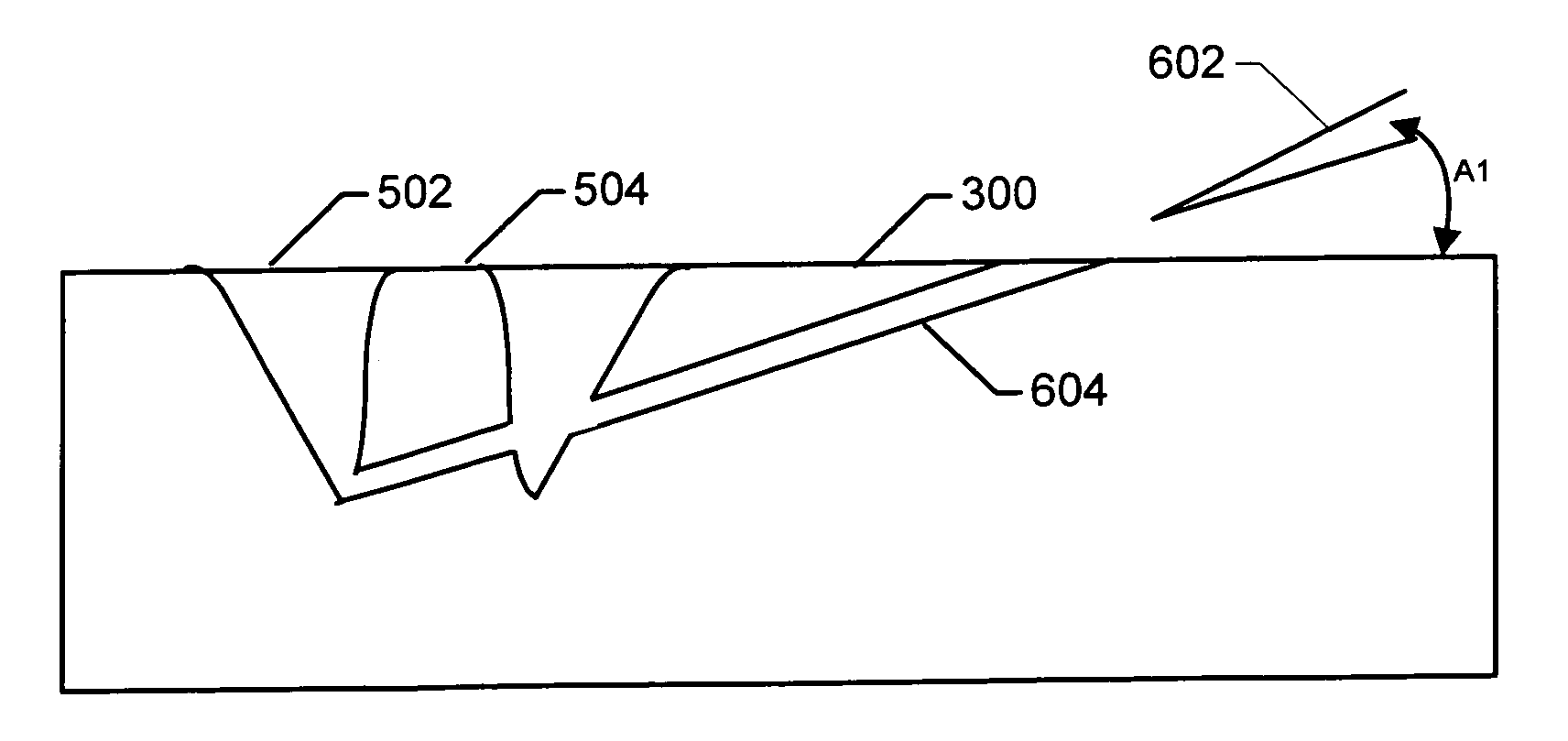
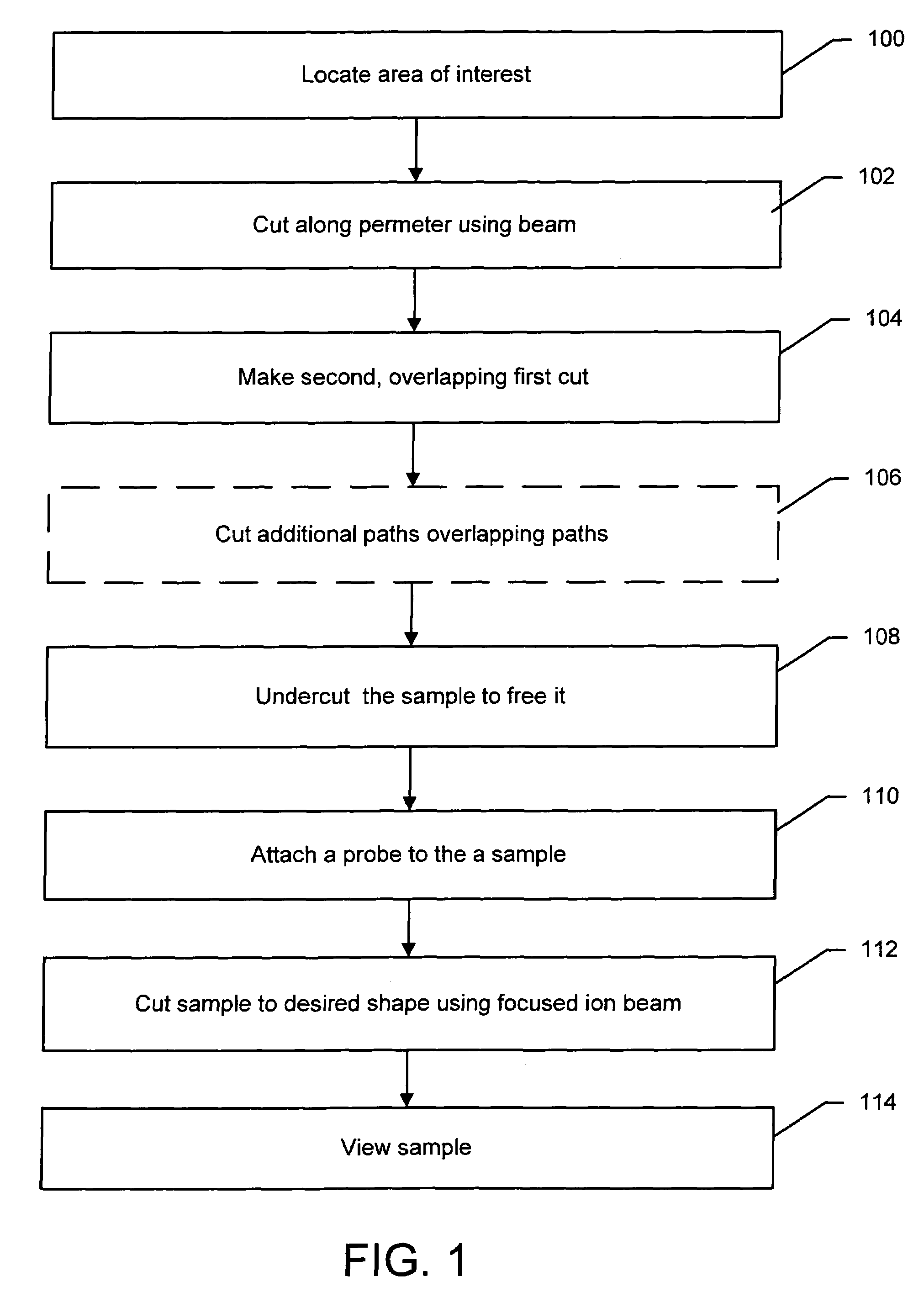
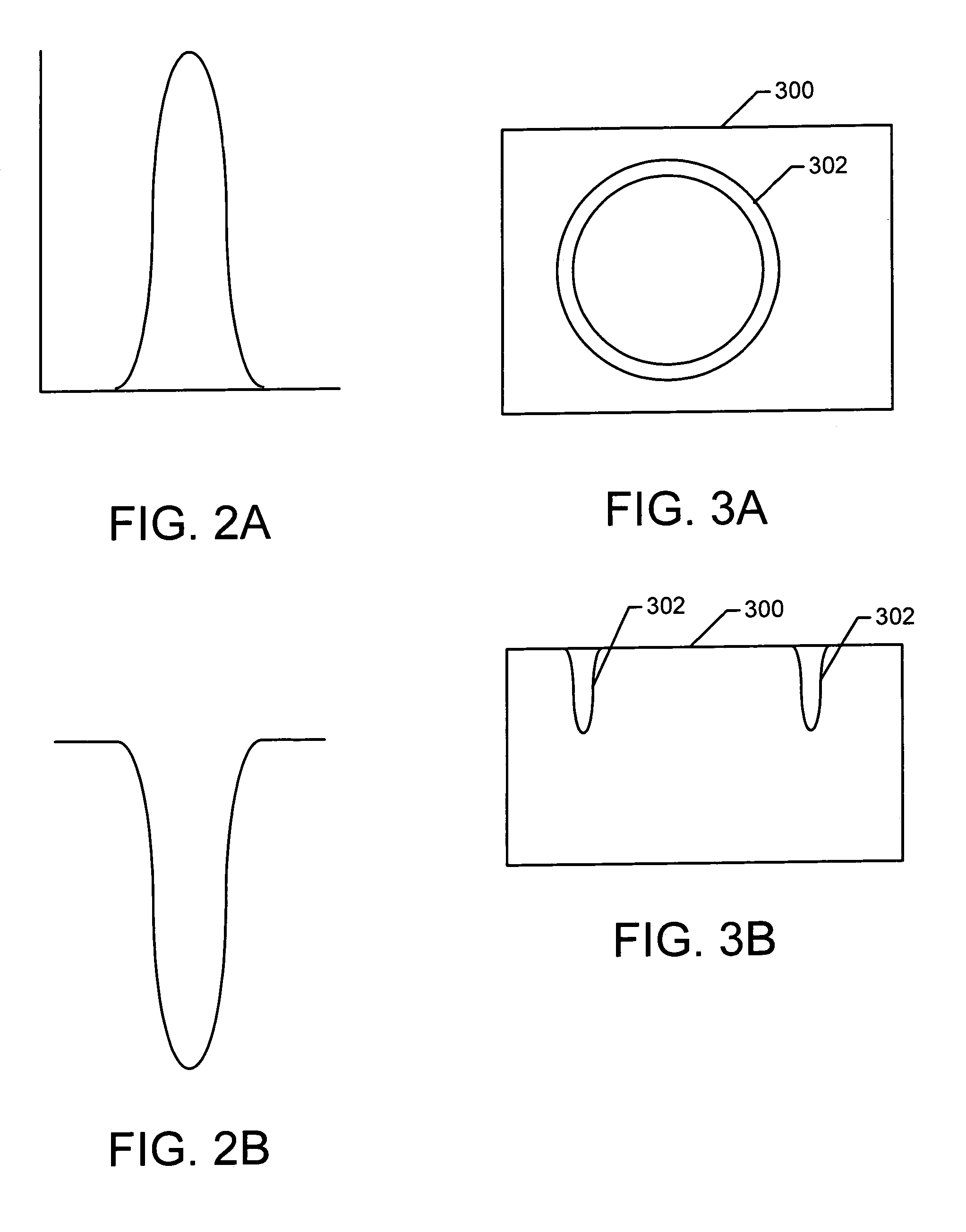
[0023]Preferred embodiments of the present invention are directed to methods and an apparatus for efficiently extracting microscopic samples from substrates. In a preferred embodiment of the present invention, a sample is extracted by making multiple, overlapping cuts using a beam, such as a focused ion beam, to create a trench around a sample, and then undercutting the sample to free it.

[0024]As discussed in greater detail below, up to a point, the sputter yield increases as beam incidence angle increases (although yield drops sharply as the incidence angle approaches 90°). The present invention takes advantage of the relationship between incidence angle and milling rate by employing a milling algorithm that maximizes beam incidence angles during milling. The milling beam is used to make a series of overlapping circumferential cuts around the object of interest. For each successive cut, the beam position overlaps a previous edge position extending from the outer diameter to an inne...


PUM

PropertyMeasurementUnit
angleaaaaaaaaaa
thickaaaaaaaaaa
thickaaaaaaaaaa

Abstract

A method of sample extraction entails making multiple, overlapping cuts using a beam, such as a focused ion beam, to create a trench around a sample, and then undercutting the sample to free it. Because the sidewalls of the cut are not vertical, the overlapping cuts impinge on the sloping sidewalls formed by previous cuts. The high angle of incidence provides a greatly enhanced mill rate, so that making multiple overlapping cuts to produce a wide trench can requires less time than making a single, deep cut around the perimeter of a sample.

Description

[0001]This application claims priority from U.S. Provisional Application No. 60 / 655,327 filed on Feb. 23, 2005 which is hereby incorporated by reference.TECHNICAL FIELD OF THE INVENTION[0002]The present invention relates to methods for extracting microscopic samples from substrates for further analysis.BACKGROUND OF THE INVENTION[0003]Transmission electron microscopes (TEMs) allow observers to see extremely small features, on the order of nanometers. A TEM sample, however, must be sufficiently thin for electrons to pass through. TEM samples are typically between about 20 nm and 200 nm thick.[0004]Several techniques are known for preparing TEM specimens. These techniques may involve either cleaving, chemical polishing, mechanical polishing, or broad beam low energy ion milling, or combining one or more of the above. The disadvantage to these techniques is that they are not site-specific and often require that the starting material be sectioned into smaller and smaller pieces, thereby...

Claims


Application Information

Patent Timeline
Patent Type & Authority Patents(United States)
IPC IPC(8): G01N23/00G21K7/00
CPCG01N1/286G01N1/32G01N23/00Y10T428/24355H01J2237/2817H01J2237/31745
Inventor GIANNUZZI, LUCILLE A.ANZALONE, PAULYOUNG, RICHARDPHIFER, JR., DANIEL W.
Owner FEI CO
Why Eureka
Try Eureka