Apparatus for detecting arc fault

a technology for detecting arc faults and apparatuses, applied in fault locations, emergency protective arrangements for limiting excess voltage/current, instruments, etc., can solve problems such as increased size of current transformers and cores, increased number of windings of coils, and strong probability of malfunction

Inactive Publication Date: 2008-10-28
SUNG SAM KYOUNG
View PDF7 Cites 10 Cited by
  • Summary
  • Abstract
  • Description
  • Claims
  • Application Information

AI Technical Summary

Benefits of technology

[0025]Therefore, the present invention has been made in view of the above problems occurring in the prior art, and it is an object of the present invention to provide an apparatus for detecting an arc fault, which prevents a malfunction generated by conventional current detection by detecting a source voltage applied onto a conductive wire to determine whether there is an arc fault.
[0026]Another object of the present invention is to provide an apparatus for detecting an arc fault, which prevents a malfunction with respect to a pseudo arc signal by dividing a current detecting route into two according to the magnitude of a load current occurring onto a conductive wire, and lessens the danger of a fire by reducing a circuit break time according to the magnitude of a load current.

Problems solved by technology

However, in order to obtain the accurate output according to the magnitude of the input current, the huge number of windings of the coil is needed and as a result the size of the current transformer and core is increased.
Although this current detecting method can easily detect the arc signal, a signal similar to the arc signal is also detected and thus there is a strong probability of a malfunction.
Furthermore, since the conventional arc fault detecting apparatus detects the arc signal by a single route without discriminating between a low current and a high current, many problems occur in setting a frequency band, or a circuit break time from an occurrence of the arc signal to the break of the circuit.

Method used


Image

  • Apparatus for detecting arc fault
  • Apparatus for detecting arc fault
  • Apparatus for detecting arc fault

Examples


Embodiment Construction

[0033]Reference will now be made in detail to the preferred embodiment of the present invention with reference to the attached drawings.

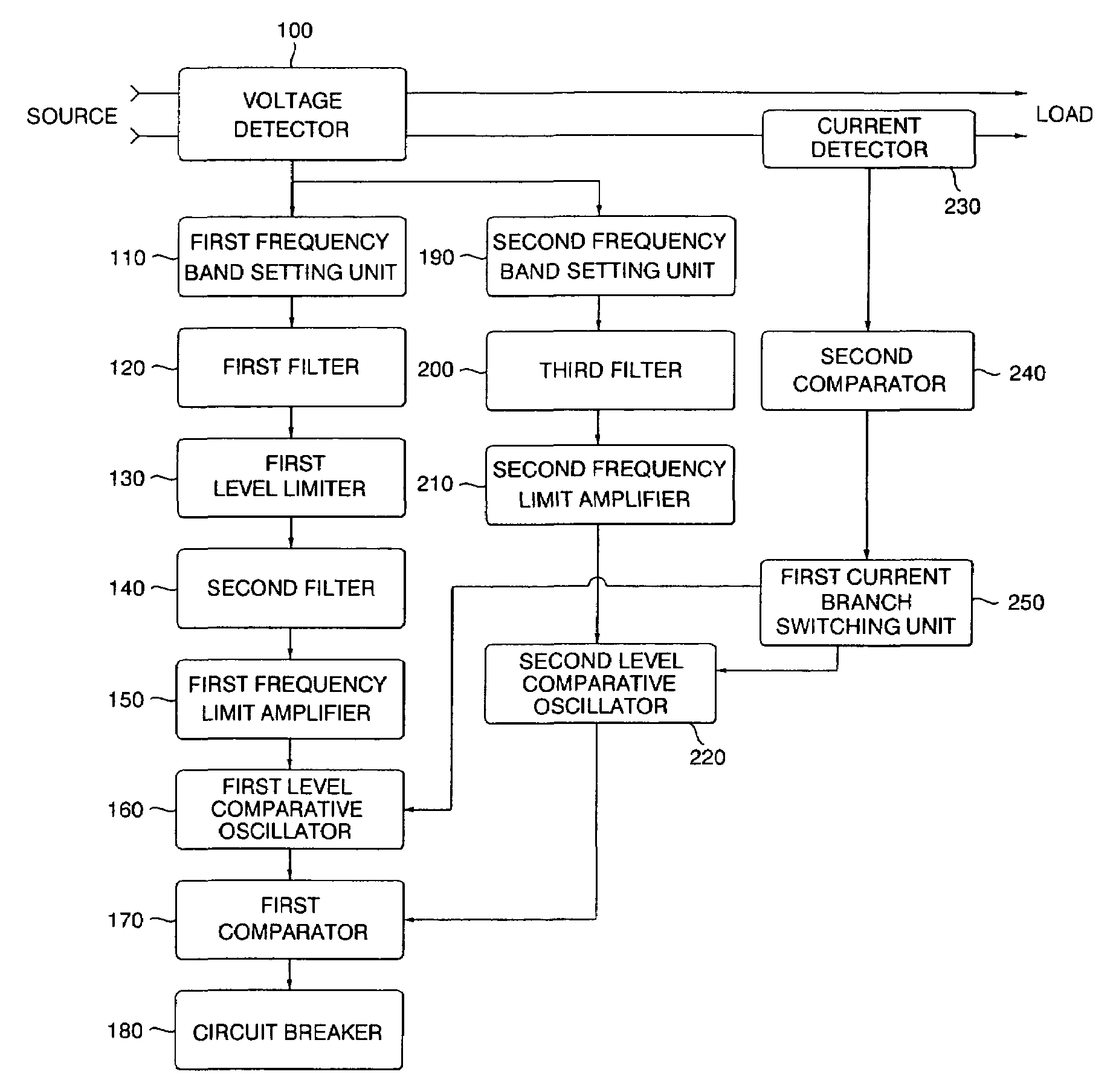
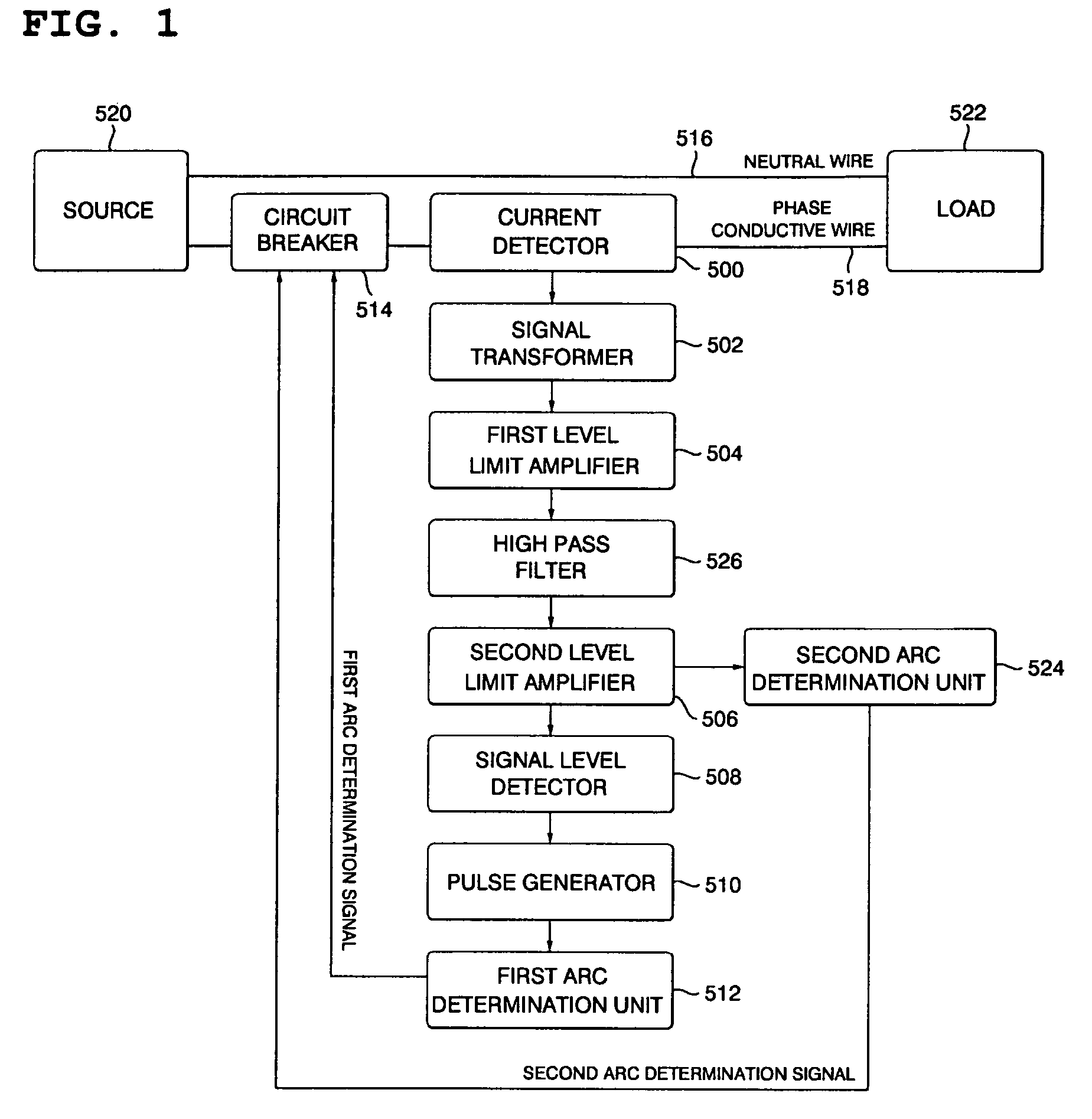
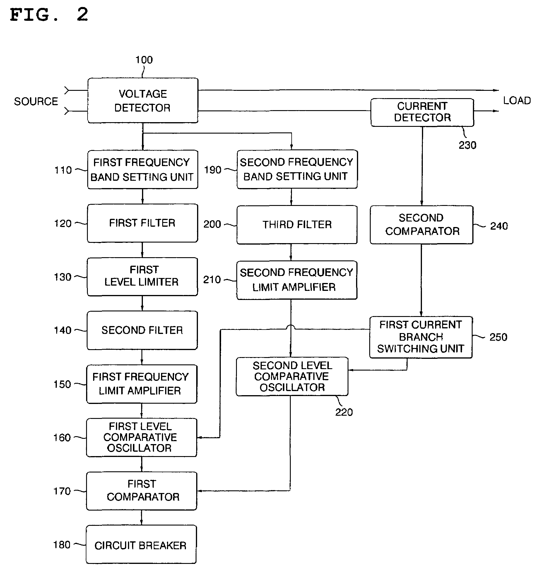
[0034]FIG. 2 is a block diagram of an apparatus for detecting an arc fault according to an exemplary embodiment of the present invention, and FIG. 3 is a detailed circuit diagram of the main parts of the apparatus of FIG. 2 according to an exemplary embodiment of the present invention.

[0035]Referring to FIG. 2, the apparatus for detecting an arc fault includes a voltage detector 100, a first frequency band setting unit 110, a first filter 120, a first level limiter 130, a second filter 140, a first frequency limit amplifier 150, a first level comparative oscillator 160, a fist comparator 170, a circuit breaker 180, a second frequency band setting unit 190, a third filter 200, a second frequency limit amplifier 210, and a second level comparative oscillator 220.

[0036]The apparatus for detecting an arc fault further includes a current detector 230, a ...


PUM


Abstract

Disclosed herein is an apparatus for detecting an arc fault, which prevents a malfunction caused by a conventional current detecting method by detecting a source voltage applied onto a conductive wire to determine whether there is an arc fault, prevents a malfunction with respect to a pseudo arc signal by dividing a current detecting route into two according to the magnitude of a load current occurring onto the conductive wire to determine whether there is the arc fault by voltage detection, and lessens the danger of a fire by reducing a circuit break time according to the magnitude of the load current. A voltage detector detects the arc fault by use of two detecting routes. Each route differs in a filtering value of a filter, presence / absence of level limit, an amplification factor of an amplifier, an accumulation value of a comparator, etc. according to the magnitude of a load current occurring on a conductive wire, thereby reducing a circuit break time.

Description

BACKGROUND OF THE INVENTION[0001]1. Field of the Invention[0002]The present invention relates to an apparatus for detecting an arc fault, and more particularly, to an apparatus for detecting an arc fault, which first prevents a malfunction caused by a conventional current detecting method by detecting a source voltage applied onto a conductive wire to determine whether there is an arc fault, prevents a malfunction with respect to a pseudo arc signal by dividing a current detecting route into two according to the magnitude of a load current occurring onto the conductive wire to determine whether there is the arc fault by voltage detection, and lessens the danger of a fire by reducing a circuit break time according to the magnitude of the load current.[0003]2. Background of the Invention[0004]Arc faults, such as a series arc fault, a parallel arc fault and a ground arc fault, are generated via an electric wiring due to physical, electric faults caused by an aged wiring, breakdown of a...

Claims


Application Information

Patent Timeline
Patent Type & Authority Patents(United States)
IPC IPC(8): H02H7/26G01R31/08
CPCH02H1/0015
Inventor SUNG, SAM KYOUNG
Owner SUNG SAM KYOUNG
Why Eureka
Try Eureka