Axial duct cooling fan

a cooling fan and axial duct technology, applied in the direction of wind motors with parallel air flow, wind motors with perpendicular air flow, liquid fuel engine components, etc., can solve the problems of affecting the overall performance of the computer system, the necessary diameter of a sleeveless fan may preclude its use, and the fan is often not suitable for electronic cooling applications

Active Publication Date: 2008-10-28
HEWLETT-PACKARD ENTERPRISE DEV LP
View PDF15 Cites 7 Cited by
  • Summary
  • Abstract
  • Description
  • Claims
  • Application Information

AI Technical Summary

Problems solved by technology

If the temperature exceeds the predetermined range (i.e., the device becomes too hot or too cold), the device may not function correctly, thereby potentially degrading the overall performance of the computer system.
Thus, when utilized for cooling high density computer systems, the necessary diameter of a shrouded fan may preclude its use.
Although providing relatively high flow rates and pressures, these fans are often not suitable for use in electronic cooling applications.
Available electric ducted fans do not meet the longevity, reliability, power consumption, acoustic, and performance requirements of electronic cooling applications.

Method used


Image

  • Axial duct cooling fan
  • Axial duct cooling fan
  • Axial duct cooling fan

Examples


Embodiment Construction

[0015]The following discussion is directed to various embodiments of the invention. Although one or more of these embodiments may be preferred, the embodiments disclosed should not be interpreted, or otherwise used, as limiting the scope of the disclosure, including the claims. In addition, one skilled in the art will understand that the following description has broad application, and the discussion of any embodiment is meant only to be exemplary of that embodiment, and not intended to intimate that the scope of the disclosure, including the claims, is limited to that embodiment.

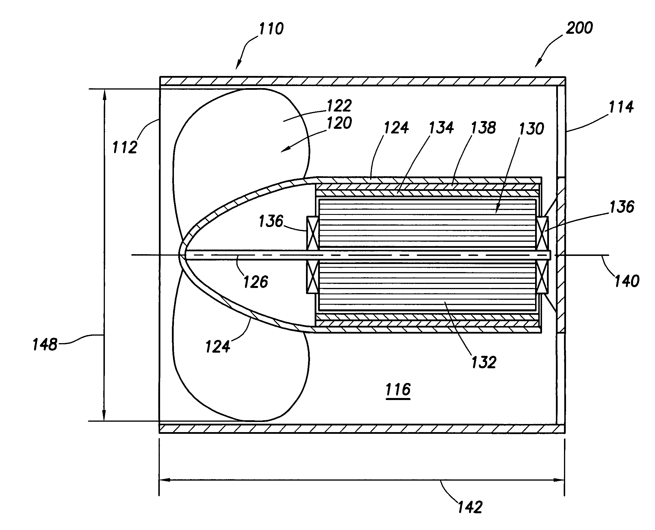
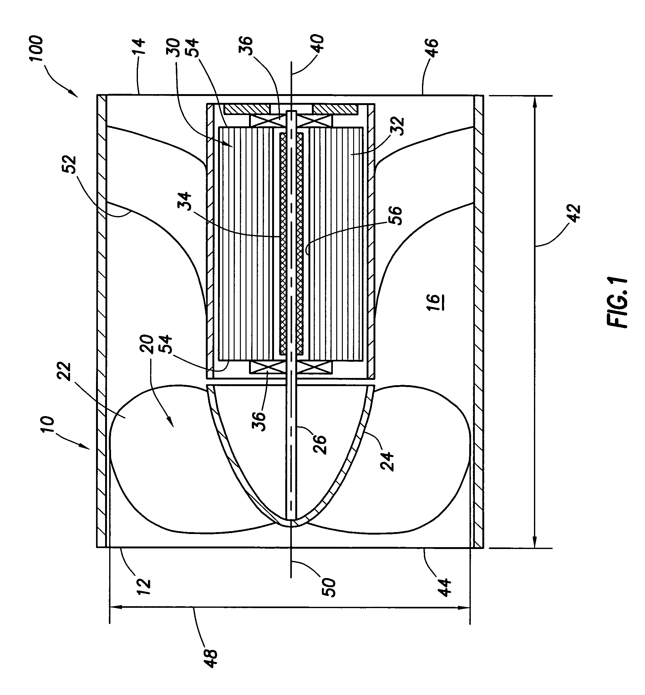
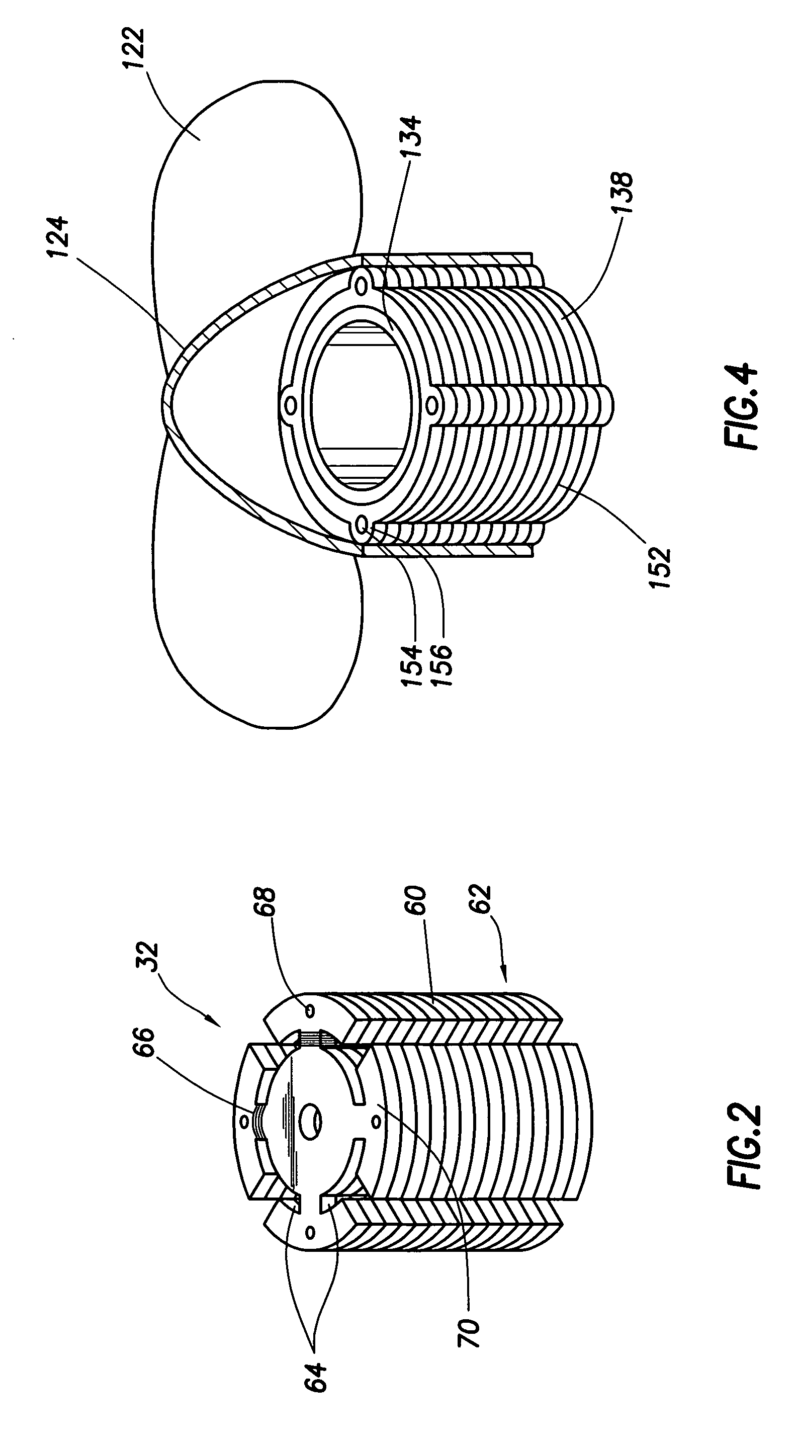
[0016]Referring now to FIG. 1, cooling fan assembly 100 comprises housing 10, blade assembly 20, and motor 30. Housing 10 comprises front side 12, rear side 14, and axial duct 16. Blade assembly 20 comprises radial blades 22, hub 24, and axle 26. Motor 30 comprises windings section 32, magnet assembly 34, and bearings 36. Motor 30 may be a high density electric motor providing an output of at least 50 Watts...


PUM


Abstract

A cooling fan comprising a housing that connects to a chassis that is operable to support an electronic component. An axial duct runs through the housing. A blade assembly is rotatably disposed within the duct and comprises a plurality of fan blades that extend radially from a hub to a fan diameter. The axial duct has a chord length at least equal to the fan diameter. A motor assembly is disposed within the axial duct and coupled to said blade assembly. The cooling fan provides a cooling capacity of at least 1.5 air horsepower per cubic inch volume of the cooling fan.

Description

BACKGROUND[0001]Computer systems include numerous electrical components that draw electrical current to perform their intended functions. For example, a computer's microprocessor or central processing unit (“CPU”) requires electrical current to perform many functions such as controlling the overall operations of the computer system and performing various numerical calculations. Generally, any electrical device through which electrical current flows produces heat. The amount of heat any one device generates generally is a function of the amount of current flowing through the device.[0002]Typically, an electrical device is designed to operate correctly within a predetermined temperature range. If the temperature exceeds the predetermined range (i.e., the device becomes too hot or too cold), the device may not function correctly, thereby potentially degrading the overall performance of the computer system. Thus, many computer systems include cooling systems to regulate the temperature ...

Claims


Application Information

Patent Timeline
Patent Type & Authority Patents(United States)
IPC IPC(8): H05K7/20H01L23/36
CPCG06F1/20H05K7/20172H05K7/20727H01L2924/0002H01L2924/00
Inventor VINSON, WADE D.FRANZ, JOHN P.NOBLETT, RONALD D.ALLEN, JOSEPH R.
Owner HEWLETT-PACKARD ENTERPRISE DEV LP
Why Eureka
Try Eureka