Above deck modular faucet assembly

a faucet and modular technology, applied in valve housings, process and machine control, instruments, etc., can solve the problems of affecting the operation of battery powered devices, and requiring expensive adapters, so as to reduce the clogging of check valves and other faucet parts.

Active Publication Date: 2008-11-04
SPEAKMAN
View PDF22 Cites 67 Cited by
  • Summary
  • Abstract
  • Description
  • Claims
  • Application Information

AI Technical Summary

Benefits of technology

[0012]A faucet according to the present invention may also have the advantage of modularity. Each element of the faucet may be serviced, separated, removed, replaced, or repaired without replacing the entire faucet or removing the faucet from its mounting. Thus, the faucet life is extended by making maintenance and service much easier, thereby saving cost and aggravation.
[0016]The modular flow control assemblies may also comprise a check valve to prevent the flow of water back toward the water source. The check valve may be placed downstream of the filter to reduce the clogging of the check valve and other faucet parts caused by particulate matter.
[0017]A faucet according to the present invention may be provided with a 6V battery or two 3V batteries. Alternatively, the faucet may be equipped with an AC power source that can be connected to the battery pack without needing a relatively expensive battery simulator.

Problems solved by technology

As a result, solenoid valves use a considerable amount of electricity to maintain them in an open position which makes them impractical for battery powered operation.
However, the Eichholz battery simulator is complex and requires an expensive adapter to fit into the battery compartment.
The prior art therefore lacks a completely above deck, modular water faucet that can be worked on without removing the faucet from the deck and from which individual parts may be removed without removing, replacing, or otherwise altering other parts or the faucet itself.

Method used


Image

  • Above deck modular faucet assembly
  • Above deck modular faucet assembly
  • Above deck modular faucet assembly

Examples


Embodiment Construction

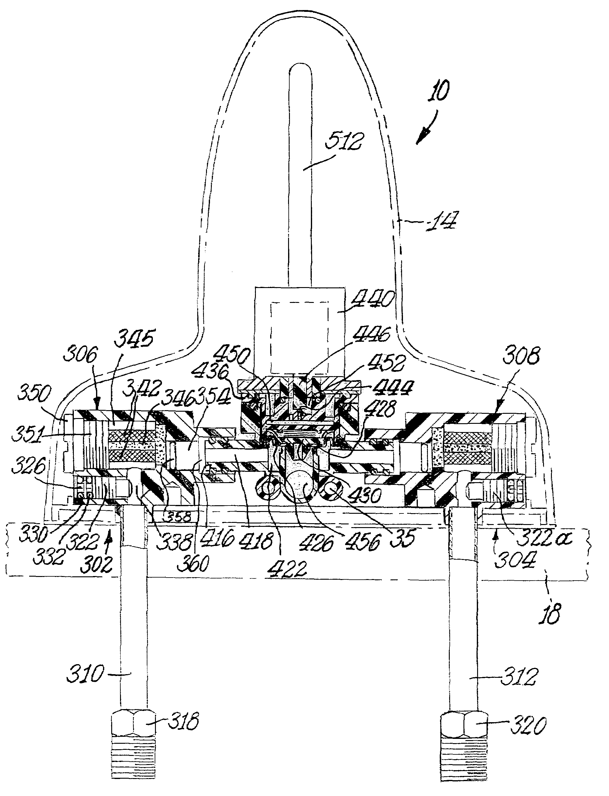
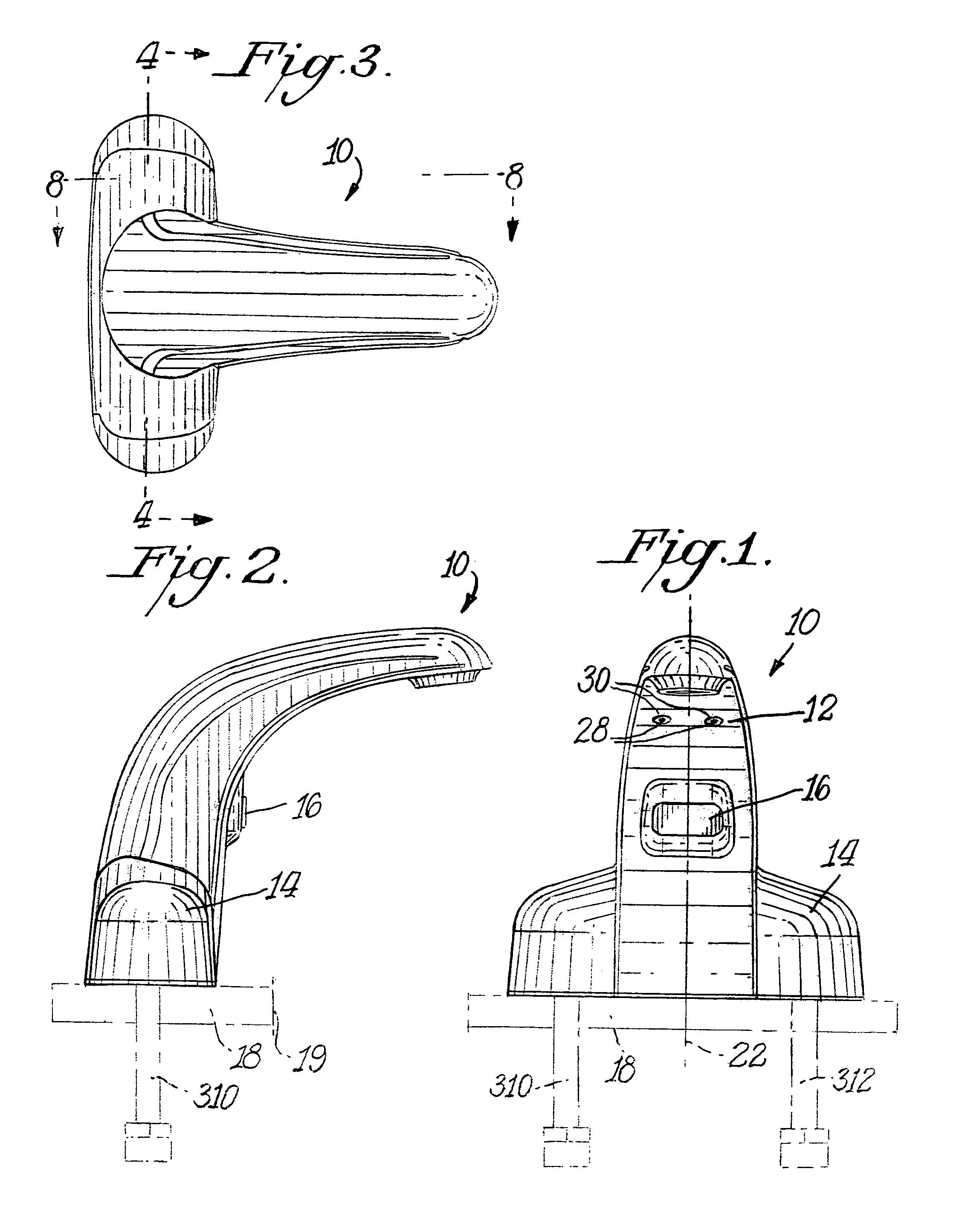
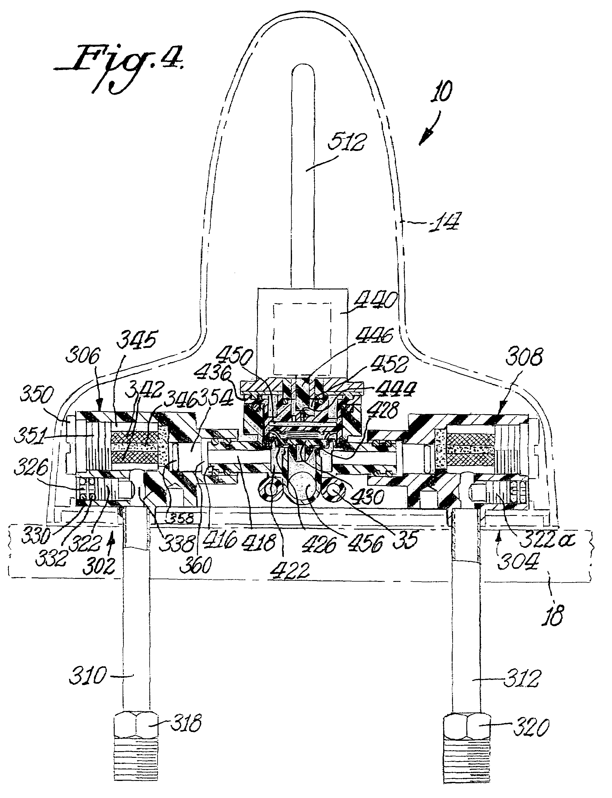
[0028]FIG. 1 illustrates a faucet according to the present invention. The faucet 10 comprises a main support body 12, an outer decorative housing body 14, and a sensor 16. Sensor 16 may be a detection mechanism known in the art for detecting the presence of hands or other objects, for example, U.S. Pat. No. 6,082,407 issued to the assignee of this application, Speakman Company of Wilmington, Del., which is incorporated herein by reference. For example, sensor 16 may comprise an IR sensor or motion sensor. The mechanisms for operating the faucet and flow of water therethrough, which will be described in greater detail below, are preferably placed within the cavity formed between support body 12 and outer housing 14, as shown in FIGS. 1-3 and 9. Main support body 12 and outer housing 14 are constructed from durable materials which retain their shape, are dimensionally stable and resist efforts of vandals. These materials may include, for example, chrome plated zinc, polymer powder coa...


PUM


Abstract

A faucet is provided comprising in-service separable parts that can be removed from the faucet without having to remove the entire housing. The faucet includes a main support housing, bolts, brackets and nuts to secure the main support body to a sink surface, two water inlets for connecting hot and cold incoming water lines. A flow control assembly is provided at each inlet to regulate the hot and cold water introduced into a mixing chamber. The valve housing includes an independent adjustable mixing valve for regulating the flow of water, an inline screen filter for removing particulate matter from the water stream, and a check valve for preventing water from returning back to the water source. Upon passing through the check valve and into water mixing housing inlets, the water is mixed in a mixing chamber. From the mixing chamber the water is regulated by a solenoid. When sink users place their hands, or other objects in front of the sensor the solenoid is activated. This permits water to flow into the faucet head portion and ultimately to the user.

Description

FIELD OF THE INVENTION[0001]The present invention relates in general to “above deck” faucets, which are characterized by having most, if not all, functional elements of the faucet above the sink deck. The present invention is further generally related to automatic service water taps or faucets which are activated electrically by a solenoid in response to an object, such as a hand, near the faucet outlet. These are often referred to as “sensor” faucets or “sensor operated faucets.”BACKGROUND OF THE INVENTION[0002]It is desirable in a variety of applications to provide a lavatory faucet which turns on and off automatically, so that the user does not have to touch the faucet to operate it.[0003]Electrically operated solenoid valves are known for use in sensor faucets. However, in a typical faucet of this type, an electric current is applied to an electromagnetic coil of a solenoid actuator to maintain a conventional solenoid valve open. Upon removal of the electric current, a spring fo...

Claims


Application Information

Patent Timeline
Patent Type & Authority Patents(United States)
IPC IPC(8): F16K11/00F16K27/12
CPCE03C1/057F16K19/006G05D23/1393E03C2201/40Y10T137/9464Y10T137/8085Y10T137/87684
Inventor PATERSON, GRAHAM H.LEE, HUI L.WALBRANDT, WILLIAM J.TRENHAM, MICHAEL D.
Owner SPEAKMAN
Why Eureka
Try Eureka