Method and apparatus for separating fluid components

a technology of fluid components and methods, applied in the direction of liquid displacement, laboratory glassware, centrifuges, etc., to achieve the effect of reducing the effectiveness of the procedure, reducing mixing, and facilitating mixing

Active Publication Date: 2008-11-04
GLOBUS MEDICAL INC
View PDF31 Cites 49 Cited by
  • Summary
  • Abstract
  • Description
  • Claims
  • Application Information

AI Technical Summary

Benefits of technology

[0017]A particular objective of the invention is to obtain a cell concentrate from whole blood (including umbilical cord blood), bone marrow aspirate, or other physiological fluid in an efficient fashion through centrifugation and the expressing of the several components. The cell concentrate preferably includes the buffy coat, some red cells, and plasma in desired ratio. The buffy coat is a thin layer that forms during centrifugation and includes mostly all of the cells other than the red blood cells. The buffy coat is known to include platelets, white cells, nucleated cells, and stem cells and may include other components as well. Because the buffy coat is a somewhat diffuse layer that is easily disrupted and mixed with the other components, which reduces the effectiveness of the procedure, an object of the invention is to provide a container that can be operated to dispense the cell concentrate without significant mixing of the desired cells with the plasma or the red blood cells. This is accomplished in the preferred embodiments primarily by providing a flow path for the cell concentrate that reduces mixing between the components. In the preferred embodiments, a disk assembly floats in a region containing an interface between plasma and the buffy coat and a diffuse interface between the buffy coat and the red cells, and assists in separating those components. As well, the disk assembly is shaped so that it forms a flow path for the components and reduces turbulence during separation of the components to prevent mixing the components during their expression.
[0018]In its preferred embodiment, a disk assembly that is allowed to float in the fluid presents a vertical gradient in the buoyant forces that cause it to assume a position in the region having the desired component, e.g., the buffy coat. This gradient is provided either by the shape of the assembly, by the use of materials of different densities, or by a combination of both. In the preferred embodiment, the disk assembly provides a conical upper surface, and an upper portion of the assembly is made of a material that is less dense than red blood cells but more dense that plasma. A lower portion of the assembly is made of a material that is denser than the red blood cells. Because of the conical shape, the buoyant force provided by the upper element at the boundary between the plasma and the red blood cells and in the region of the buffy coat is a non-linear function of the distance by which the upper element extends into the plasma. The density gradient of the fluids in the boundary region is large, and the use of a floating element with a density gradient also has been found to be beneficial.
[0019]The disk assembly according to the invention is designed to encompass both a desired component and a predetermined volume of fluid surrounding the desired component. In the preferred embodiment, the disk assembly comprises two floating parts that are movable relative to each other whereby the entire assembly is caused to assume a desired position after centrifugation, and one part moves toward the other during expression of the fluids to express a desired component or components, e.g., the buffy coat and a predetermined volume of plasma. This structure allows the user to obtain a cell concentrate comprising the buffy coat mixed with plasma at a desired increased concentration.
[0020]The invention also relates to perfecting mechanical features, such as a handle for a plunger that accommodates placing the syringe in a centrifuge, and a stand for holding the syringe after centrifugation for facilitating expression of the components. The handle may be detachable or flexible whereby the distance by which it extends from the end of the barrel when the syringe is full is greatly reduced.
[0022]It is a further object of this invention to provide a syringe for withdrawing fluids from a container or from the patient, for being placed directly into a centrifuge, and for expressing the separated components in serial fashion with minimal mixing.

Problems solved by technology

The device may, however, be a container of other configurations capable of being placed in a centrifuge and not necessarily designed to operate as a syringe.

Method used


Image

  • Method and apparatus for separating fluid components
  • Method and apparatus for separating fluid components
  • Method and apparatus for separating fluid components

Examples


Embodiment Construction

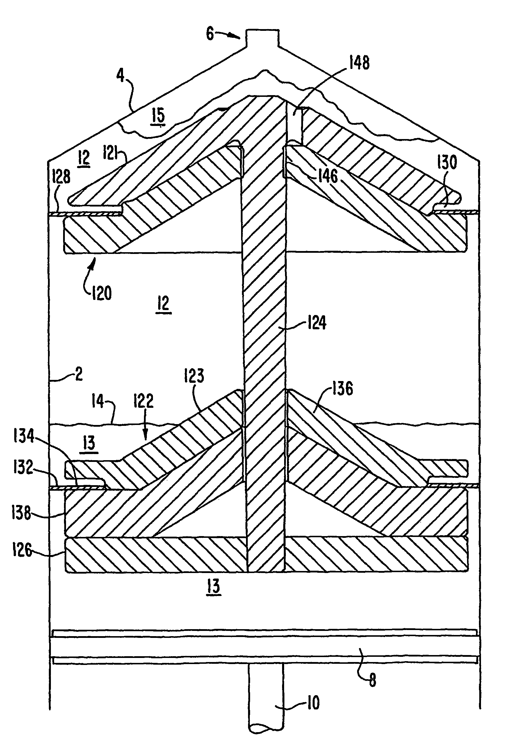
[0035]The invention will be described below in accordance with its operation as a syringe. Use with a syringe is advantageous because it allows the user to withdraw the physiological fluid into the syringe, place the syringe directly into a centrifuge for centrifugal processing, and then to express the several components from the syringe into separate containers. As such, this procedure requires only a single container without intermediate decanting steps. It will be understood, however, that many features of the invention do not require operation with a syringe or a single container and that the disk assembly to be described below may be used in combination with other containers as well.

[0036]A floating element that automatically assumes a position just below the buffy coat is disclosed in WO 01 / 83068. The disk disclosed there is useful to separate the components of physiological fluids by centrifugation and finds its primary utility in structures that separate the components after...


PUM

PropertyMeasurementUnit
densitiesaaaaaaaaaa
stabilityaaaaaaaaaa
densityaaaaaaaaaa

Abstract

A floating element for separating components of a physiological fluid comprises two parts that are relatively movable. The two parts define a prescribed volume between them when at their maximum separation, and one of the parts may be moved toward the other to express the fluid contained in the volume between the parts. The parts are made of materials having densities so that they assume a desired position in the fluid to allow selected components to be easily obtained are expressed.

Description

[0001]This application is the national stage of International Application No. PCT / US2004 / 015654, filed May 19, 2004 , which was published in English, and claims priority Of U.S. Provisional Application No. 60 / 471,352 , filed May 19, 2003.TECHNICAL FIELD[0002]This invention relates to a unique element that floats in a physiological fluid undergoing centrifugation and assumes a location encompassing the boundary region between two components of different densities, and facilitates the isolation of a desired component found in the boundary region. Specifically, the floating element greatly facilitates the isolation and separation of the buffy coat from plasma and red blood cells.[0003]Another aspect of the invention is the provision of a device for use both as a syringe for withdrawing physiological fluids and as a chamber for separating the components of the fluids. In its preferred embodiments, the invention is a syringe configured to withdraw fluids from a patient in known fashion a...

Claims


Application Information

Patent Timeline
Patent Type & Authority Patents(United States)
IPC IPC(8): B04B1/00B01L3/02B01L3/14B01L99/00G01N
CPCB04B15/00B01L3/50215A61M5/31513A61M5/31515B01L2400/0478B01L3/021
Inventor ELLSWORTH, JAMES R.MCGOVERN, PAULKIBBE, MARK L.
Owner GLOBUS MEDICAL INC
Why Eureka
Try Eureka