System utilizing the earth's magnetic field to generate a force in opposition to the force of gravity

a technology of earth magnetic field and force, applied in the direction of superconducting magnets/coils, magnetic bodies, machines/engines, etc., can solve the problems of large and bulky vehicles, inability to move with any effective speed, and inability to control gravitation, so as to reduce the apparent weight of objects and reduce the apparent “load weight”

Active Publication Date: 2008-11-04
BELOW III JOHN F AND BELOW HOLLY E AS TRUSTEES OF THE BELOW 1999 TRUST DATED SEPTEMBER 15 1999
View PDF1 Cites 9 Cited by
  • Summary
  • Abstract
  • Description
  • Claims
  • Application Information

AI Technical Summary

Benefits of technology

[0017]In both the apparatus and method the generation of a force in opposition to the force of gravity, a lifting force, is accomplished by utilizing a loop of superconducting material cooperable with the Earth's magnetic field. Under the right conditions, a current could be induced in a ring or loop of superconducting material and the material would “float” or levitate indefinitely, assuming of course that technology has advanced to such a state. In any event, the present invention utilizes the present state of technology, including the technology of superconductors, to apply an upward force on an object with the effect of reducing the apparent weight of the object. Someday it is anticipated that developing technologies will reach a state enabling lifting or levitation of an object. In any event, the present invention as disclosed and claimed herein has utility in that the apparent “load weight” of an object is reduced to at least some degree by utilizing the principles of the invention.

Problems solved by technology

It is unlikely that gravitation, itself, will be controllable since there are no current practical examples of antigravity or even gravitational manipulation.
The drawback is that these vehicles are large and bulky and cannot move with any effective speed.
These can be effective, maneuverable craft, but they consume a great amount of energy to maintain flight and are highly complex machines.
They are somewhat limited to vertical motion and are less practical as a means of transport within the Earth's gravitational field.
This has been shown to be effective but travel is limited to magnetic rail beds that must be constructed and supported on the ground.
Therefore it takes a very high amount of current to yield any meaningful lift force.
This kind of current density, however, is not out of the realm of possibility for a superconductor.

Method used


Image

  • System utilizing the earth's magnetic field to generate a force in opposition to the force of gravity
  • System utilizing the earth's magnetic field to generate a force in opposition to the force of gravity
  • System utilizing the earth's magnetic field to generate a force in opposition to the force of gravity

Examples


Embodiment Construction

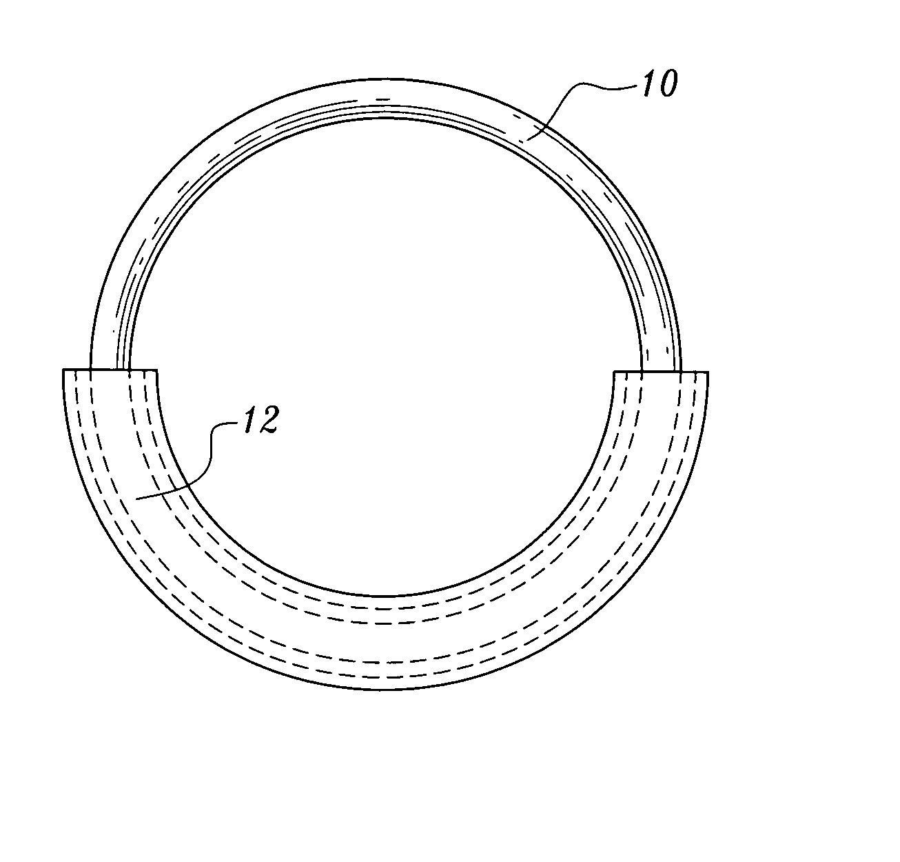
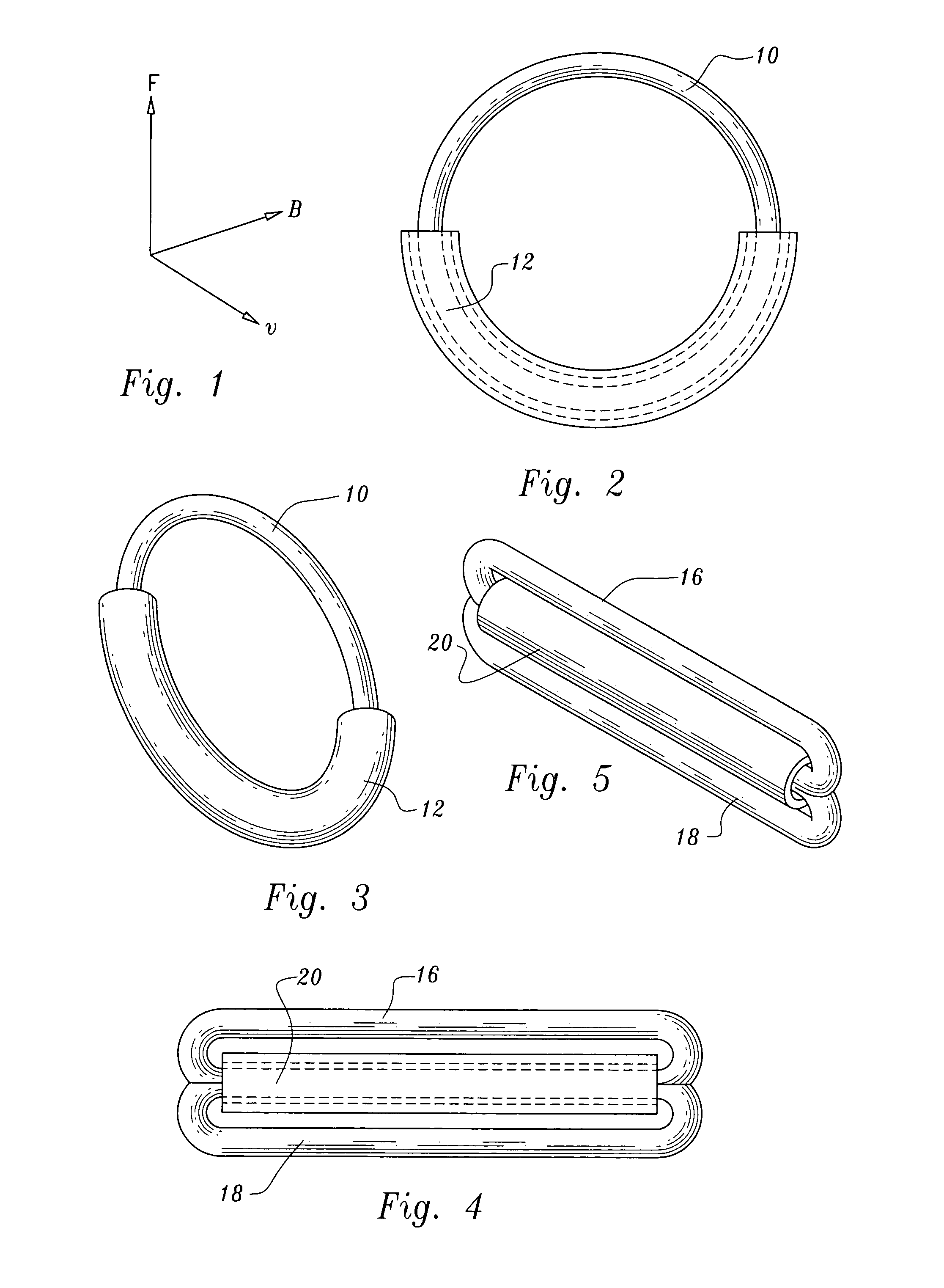
[0037]Under the right conditions a current could be induced in a ring or loop of superconducting material and that material would “float” or levitate indefinitely.

[0038]Some of the considerations for this to happen are:

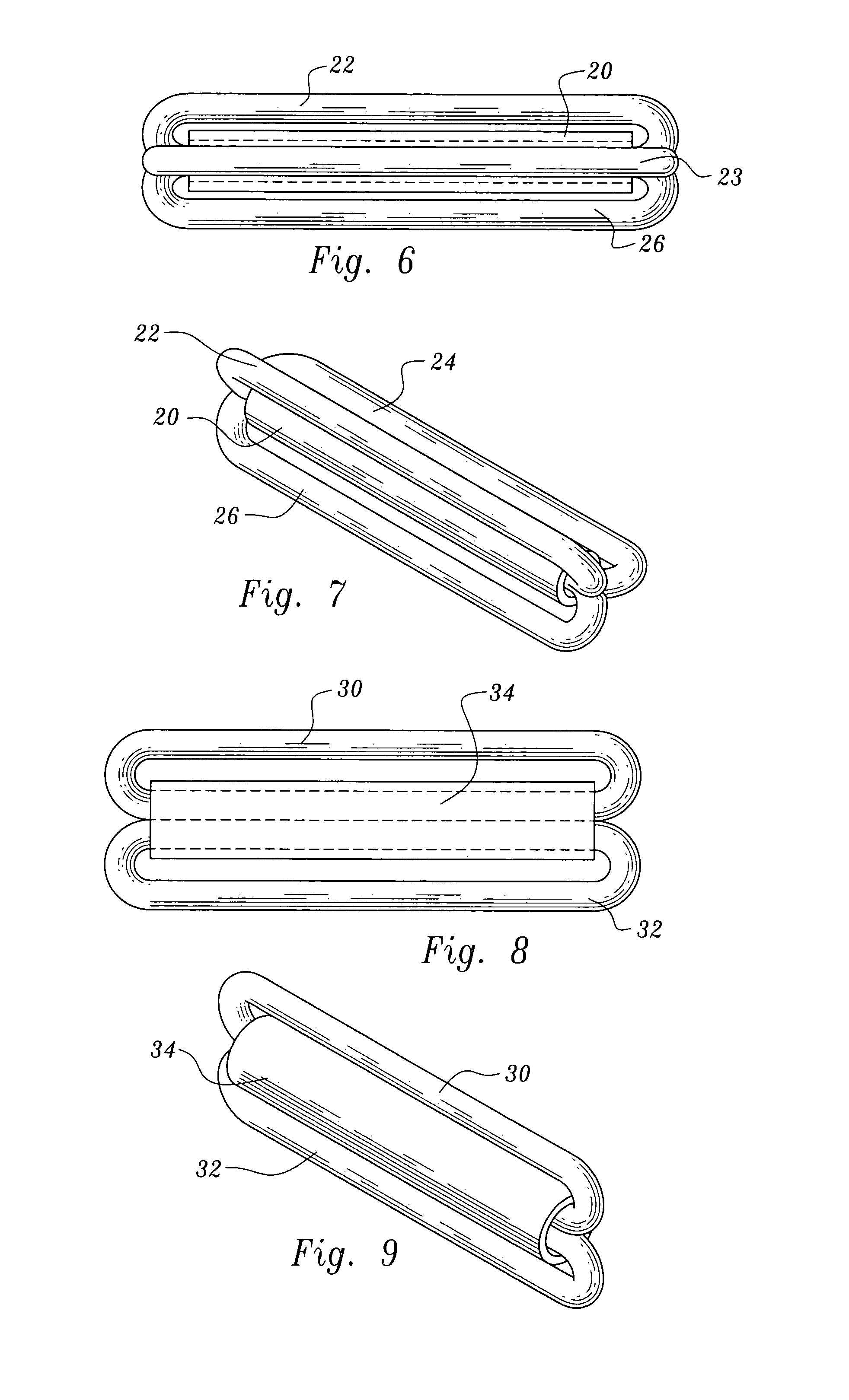
[0039]1. Current traveling west to east would produce an upward force or lift and current traveling east to west would produce a downward force. To produce a net lifting force the portion of the superconducting loop where the current moves east to west would have to be shielded from the Earth's magnetic field.

[0040]A magnetic shielding material, such as Mu-metal could be used for this. Mu-metal is a nickel iron alloy (77% Ni, 15% Fe, plus Cu and Mo) that has the property of shielding external magnetic fields up to 0.1 Tesla, thus making it a very effective shield of the Earth's magnetic field of 0.0001 Tesla.

[0041]2. The current loop and shielding would have to be maintained in an orientation of west to east to obtain maximum lift. Lift could be controlled by either c...


PUM

PropertyMeasurementUnit
magnetic fieldaaaaaaaaaa
levitation forceaaaaaaaaaa
magnetic fieldaaaaaaaaaa

Abstract

A loop of superconducting material forms a continuous current flow path. A portion of the loop is shielded from the Earth's magnetic field and another portion is unshielded. Charged particles flowing through the unshielded portion cooperate with the Earth's magnetic field to create an upward force on said loop.

Description

TECHNICAL FIELD[0001]This invention relates to apparatus utilizing the Earth's magnetic field to apply a force to the apparatus in opposition to the force of gravity. The invention also encompasses a method.BACKGROUND OF THE INVENTION[0002]Geo-Levitronics[0003]There is a common perception that vehicles of the future will be capable of hovering and flying. This ability to levitate would provide significant benefits to military, commercial, and personal transportation. If man can make an object levitate it will likely be by applying currently known science. It is unlikely that gravitation, itself, will be controllable since there are no current practical examples of antigravity or even gravitational manipulation. Some other mechanism will have to be employed to oppose the gravitational force that holds matter to the Earth. The term “Geo-levitronics” is employed herein for the study of such a mechanism and the names “Geo-levitron” or “Geolev” are used to describe a device that could be...

Claims


Application Information

Patent Timeline
Patent Type & Authority Patents(United States)
IPC IPC(8): H01F6/00
CPCB64C39/001B64G1/409F03H99/00H01F6/06B64C29/0008
Inventor BELOW, JOHN
Owner BELOW III JOHN F AND BELOW HOLLY E AS TRUSTEES OF THE BELOW 1999 TRUST DATED SEPTEMBER 15 1999
Why Eureka
Try Eureka