
Decoding device and decoding program for video image data

a video image and decoding technology, applied in the field of compressing video images, can solve the problems of reducing memory access performance, increasing the size of cache memory, and requiring a great deal of calculations in the decoding process of video images, so as to reduce the occurrence rate of cache misses and improve memory access performan

Inactive Publication Date: 2008-11-04
FUJITSU LTD
View PDF4 Cites 6 Cited by
  • Summary
  • Abstract
  • Description
  • Claims
  • Application Information

AI Technical Summary

Benefits of technology

The present invention aims to improve memory access performance during video image data decoding. It achieves this by reducing the occurrence rate of cache misses and by preloading data from a reference macroblock. The device uses a motion compensation technique and a cache memory to temporally store image data. The device also includes a reference macroblock position determining unit and a preload address specifying unit to optimize data preload from the cache memory. Overall, the invention improves video image data decoding performance by reducing cache misses and optimizing data preload.

Problems solved by technology

As described above, decoding processes of a video image requires a great deal of calculations due to a very large amount of data included therein.
However, the size of the reference frame image is much larger than that of the cache memory and also, there are various limitations about increase of the size of the cache memory in view of the requirement for a lower cost and a lower power consumption of the devices.
As described above, because there are limitations on a size of a cache memory, the occurrence rate of cache miss is raised, therefore, there is a problem that memory access performance declines due to a prolonged time for loading of data to an external memory, a main memory, or the like in case that a cache miss occurs.
Especially in a video image data decoding device employing a motion compensation technique, there is a problem that the decoding processes in a higher speed can not be realized due to a decline of memory access performance caused by the occurrence of a cache miss, because such a decoding device accesses to the reference frame image frequently.
However, even in a configuration that such a preload is conducted, there is a problem that a necessary preload of a region is not conducted or a loaded region is again preloaded prior to the region not preloaded, depending on a position of a reference macroblock, leading to a decline of memory access performance.
Specifically, in FIG. 4, because a preload specifying address is set to a front address of a line of a reference macroblock (reference rectangular region), while region “A” as a region not beyond the cacheline is preloaded, region “B” which is beyond the cacheline is not preloaded, therefore, a cache miss is caused after the preload, leading to a decline of memory access performance.
This situation results in an occurrence of cache miss and may cause the decline of memory access performance.
However, these techniques do not solve a problem that a region beyond a cacheline boundary is not preloaded as explained in FIG. 4, or a problem that an already preloaded region is preloaded prior to the region not preloaded as explained in FIG. 5.

Method used


Image

  • Decoding device and decoding program for video image data
  • Decoding device and decoding program for video image data
  • Decoding device and decoding program for video image data

Examples


Embodiment Construction

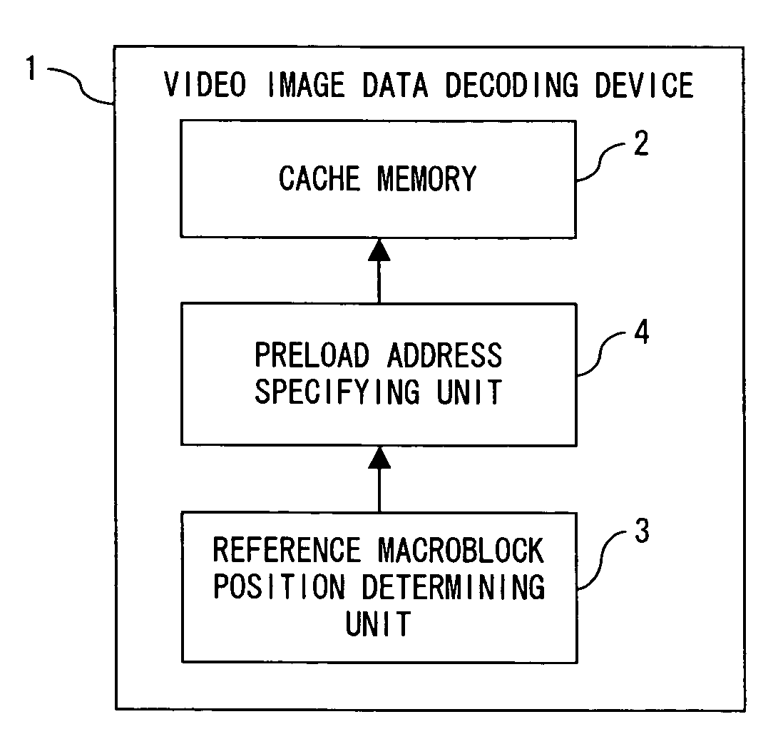
[0042]FIG. 6 is a block diagram showing a principle configuration of a video image data decoding device of the present invention. In FIG. 6, a decoding device 1 employs a motion compensation technique and comprises a cache memory 2, a reference macroblock position determining unit 3 and a preload address specifying unit 4.

[0043]The cache memory 2 temporally stores video image data. The reference macroblock position determining unit 3 determines a position of a reference macroblock on a reference frame corresponding to a macroblock to be decoded. The preload address specifying unit 4 determines whether or not a reference macroblock includes a cacheline boundary when data of the reference macroblock is not stored in the cache memory 2, and specifies a position of the cacheline boundary as a front address for the data preload from a memory storing the data of the reference macroblock when the reference macroblock includes the cacheline boundary.

[0044]The video image data decoding devic...


PUM


Abstract

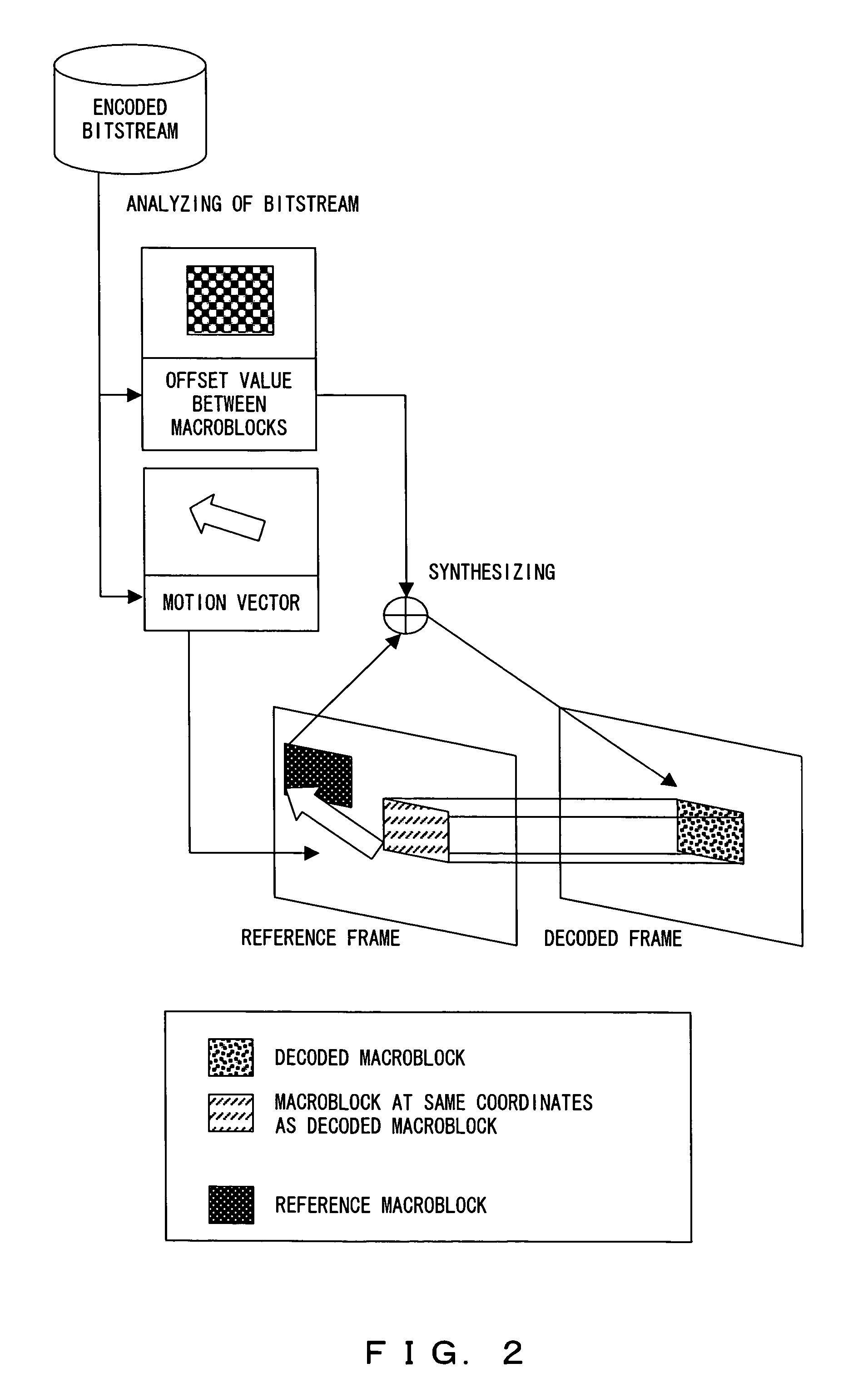
A decoding device comprises a cache memory for temporally storing video image data, a unit for determining a position of a reference macroblock corresponding to macroblock to be decoded based on a motion vector obtained by analyzing an encoded bitstream, and a unit for determining whether or not a reference macroblock includes a cacheline boundary when data of the reference macroblock is not stored in the memory and for specifying the position of the boundary as a front address for the data preload from a memory storing the data of the reference macroblock.

Description

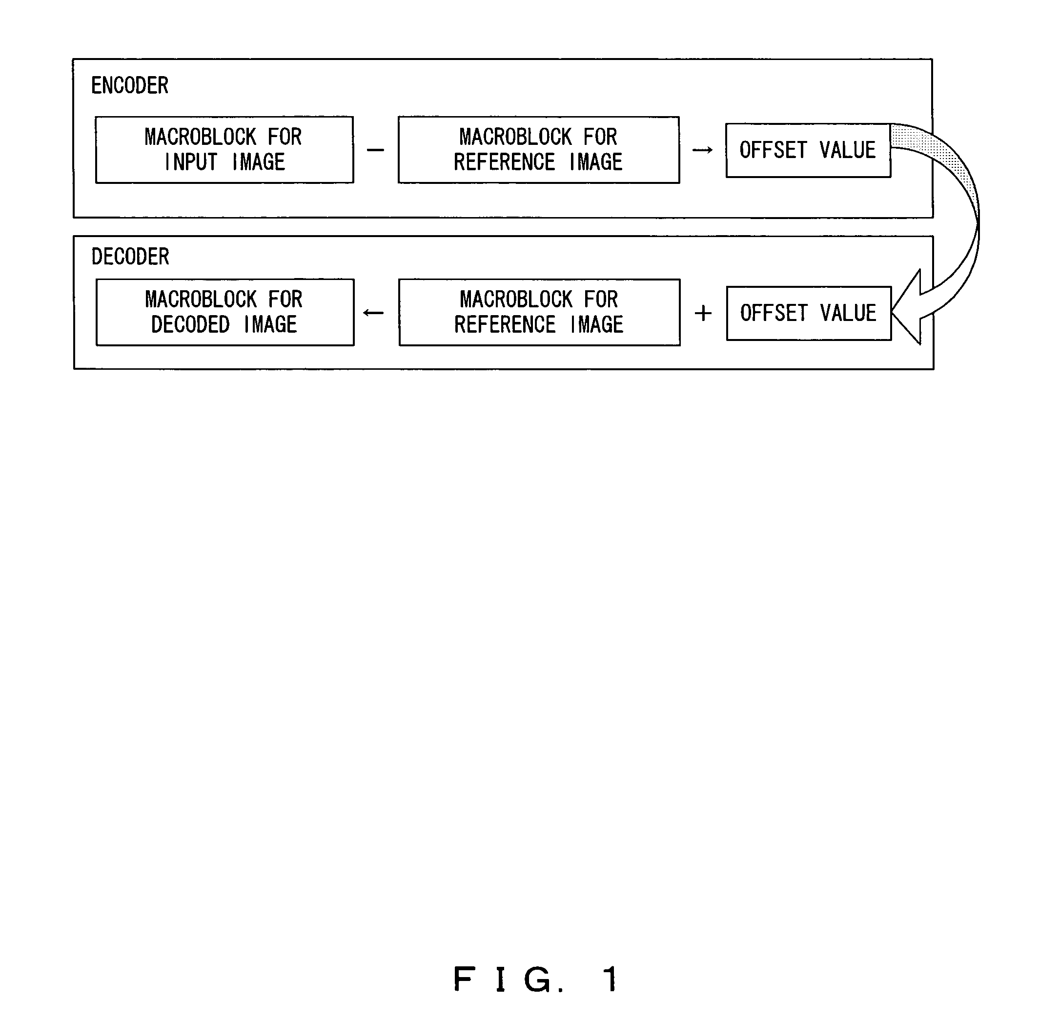
BACKGROUND OF THE INVENTION[0001]1. Field of the Invention[0002]The present invention relates to a method of compressing a video image, and more particularly to a decoding device and a decoding program for video image data in which a decoding processing is conducted, in a high speed, on a bitstream being encoded by using interframe prediction method on a processor system including a cache memory.[0003]2. Description of the Related Art[0004]In recent years, video image data is expressed in digital data and is used for such purposes as an image distribution service by being stored in digital media or via network communications, digital television broadcastings using satellites, or the like. Generally, a video image includes a large data amount. Therefore, a video image is compressed in accordance with a compression encoding technique in order to reduce the data amount, and is decoded for the reproduction of the video image. In MPEG (Moving Picture Expert Group) system as an internatio...

Claims


Application Information

Patent Timeline
Patent Type & Authority Patents(United States)
IPC IPC(8): H04N7/12H04N19/102H04N19/50H04N19/134H04N19/167H04N19/176H04N19/189H04N19/423H04N19/44
CPCG06F12/0862G06F12/0875H04N19/51H04N19/433H04N19/44H04N19/423H04N19/61
Inventor YAMASHITA, KAZUHIROORITA, KENJI
Owner FUJITSU LTD
Learn More