Power meter

a power meter and digital technology, applied in the field of electric power meters, can solve the problems of affecting the accuracy of the readings produced by the meter, reducing the overall efficiency of the power distribution system, and the actual transformer is not ideal,

Active Publication Date: 2008-11-04
VERIS INDS
View PDF3 Cites 70 Cited by
  • Summary
  • Abstract
  • Description
  • Claims
  • Application Information

AI Technical Summary

Problems solved by technology

While the circuit's reactive elements, capacitors and inductors, do not dissipate significant power, they do produce voltage drops and current draws that reduce the overall efficiency of the power distribution system.
However, actual transformers are not ideal transformers and the magnetization of the core of the current transformer produces errors that affect the accuracy of the readings produced by the meter.
Current transformer error comprises a phase error and a ratio error.
In any event, considerable additional data processing resources are required to adjust each sample of the secondary winding current for the phase and error ratio produced by the current transformer.
Providing a dedicated DSP to perform sampling substantially increases the data processing resources and the cost of the sampling unit.
While microprocessors are commonly used to perform multiple tasks, interrupt latency makes combining real time tasks, such as those performed by the sampling unit of a power meter, with the other data processing tasks related to meter operation problematic.
Interrupt latency, the interval between the assertion of an interrupt request and the initiation of the interrupt service routine for the asserted interrupt, makes the timing of the initiation of the execution of the interrupt uncertain, making precise timing of real-time tasks, such as sampling, unreliable, and, as a result, potentially making the output of the meter inaccurate.

Method used


Image

  • Power meter
  • Power meter
  • Power meter

Examples


Embodiment Construction

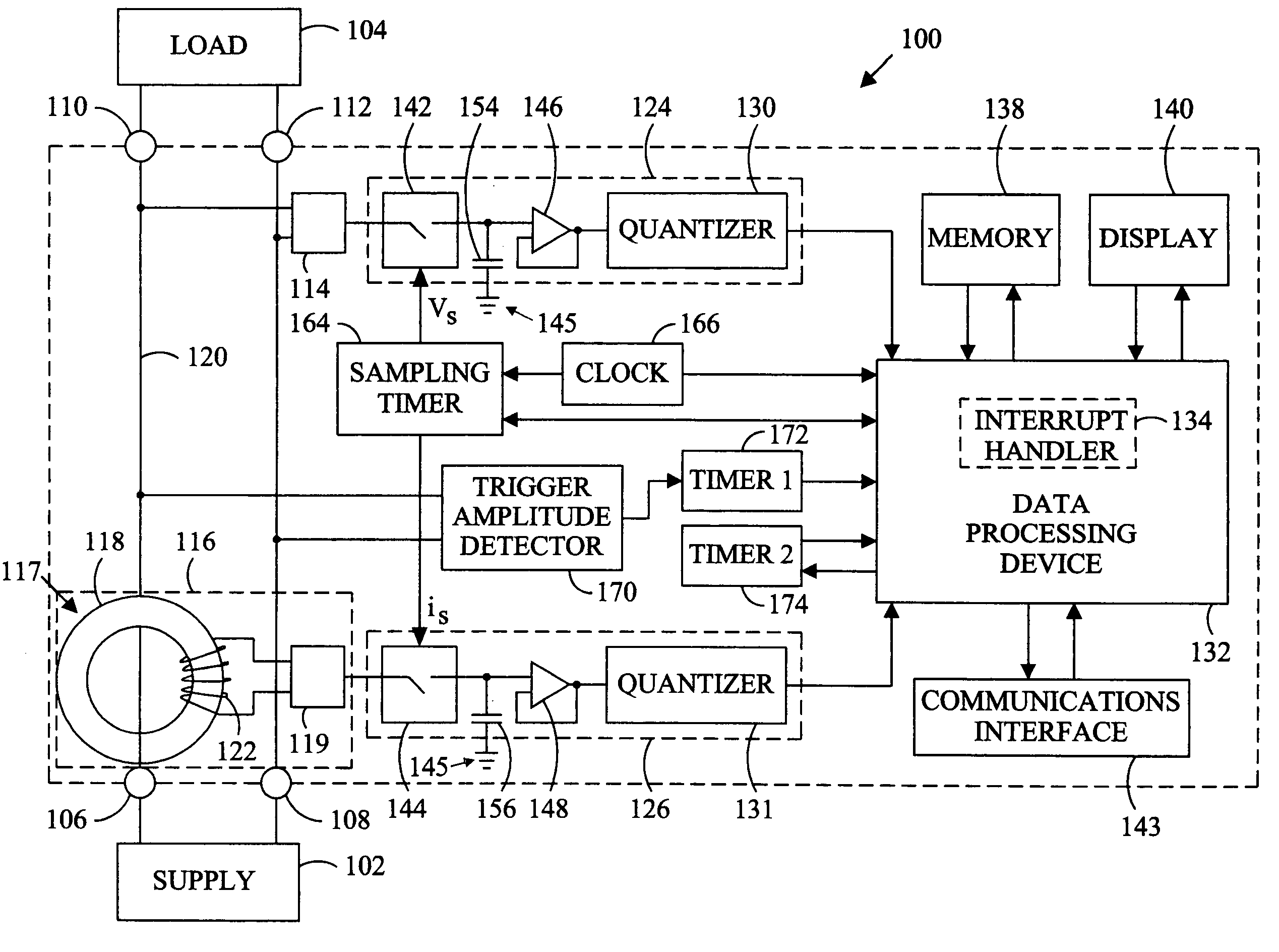
[0060]Referring in detail to the drawings where similar parts of the invention are identified by like reference numerals, and, more particularly to FIG. 3, electric power consumption is monitored by a digital electrical power meter 100 adapted for connection between a supply 102 and a load (or loads) 104 of an electrical distribution system via input terminals 106, 108 and output terminals 110, 112. The supply voltage is sensed through a voltage transducer 114, typically a voltage divider resistor network, and the load current is sensed by a current transducer 116, commonly a current transformer 117 and a resistor network 119. A current transformer 117 typically comprises a secondary winding 122 comprising multiple turns of conductive wire wrapped around the cross-section of a toroidal core 118 and a primary winding comprising a conductor 120 connecting a supply terminal 116 to a load terminal 110 and passing through the aperture in the center of the toroidal core 118. The primary w...


PUM


Abstract

The computational resources of a digital power meter can be reduced by utilizing an interrupt requested in anticipation of interrupt latency to perform real-time tasks, an approximation of a root mean square load current at an earlier time to compensate for a phase shift between the load current and the current transducer output, and an amplitude that is neither zero nor maximum to distinguish the cycles of a harmonically distorted waveform.

Description

CROSS-REFERENCE TO RELATED APPLICATIONS[0001]This application claims the benefit of U.S. Provisional App. No. 60 / 635,594, filed Dec. 13, 2004.STATEMENT REGARDING FEDERALLY SPONSORED RESEARCH OR DEVELOPMENT[0002]Not applicable.BACKGROUND OF THE INVENTION[0003]The present invention relates to electric power meters and, more particularly, to a digital power metering apparatus and method.[0004]Electric power is typically generated at a remote, central generating facility and transported to the consumer over a distribution system. To reduce power transportation losses, a step-up, sub-transmission transformer is used to increase the voltage and reduce the current for transmission over a transmission line. The actual transmission line voltage usually depends on the distance between the sub-transmission transformers and the consumers of the electricity but is commonly in the range of 2-35 kilo-volts (“kV”). Distribution substation transformers and distribution transformers of an electric ut...

Claims


Application Information

Patent Timeline
Patent Type & Authority Patents(United States)
IPC IPC(8): G06F19/00
CPCG01R22/10
Inventor BRUNO, DAVID A.
Owner VERIS INDS
Why Eureka
Try Eureka