Distributed perimeter security threat confirmation

a perimeter security and threat confirmation technology, applied in the field of perimeter security networks, can solve the problems of central control system generating false alarms, time and resources wasted in dispatching personnel to investigate non-threatening events, and inability to accurately evaluate threat evaluation processes, etc., to achieve the effect of reducing the time and effort required of non-threatening events, reducing the processing resources required of central control systems, and improving scalability and efficiency of operation

Active Publication Date: 2008-11-11
ALLISON SYST
View PDF32 Cites 21 Cited by
  • Summary
  • Abstract
  • Description
  • Claims
  • Application Information

AI Technical Summary

Benefits of technology

[0020]Advantageously, embodiments of the invention provide for distributing threat evaluation to the sensor systems of a perimeter security network. In an advantage, the processing resources required of a central control system are reduced. In addition,

Problems solved by technology

One problem associated with this approach is that dispatching personnel to investigate non-threatening events wastes time and resources.
However, threat evaluation processes often times lack accuracy.
For example, a single

Method used


Image

  • Distributed perimeter security threat confirmation
  • Distributed perimeter security threat confirmation
  • Distributed perimeter security threat confirmation

Examples


first embodiment

Configuration and Operation

FIGS. 1-3

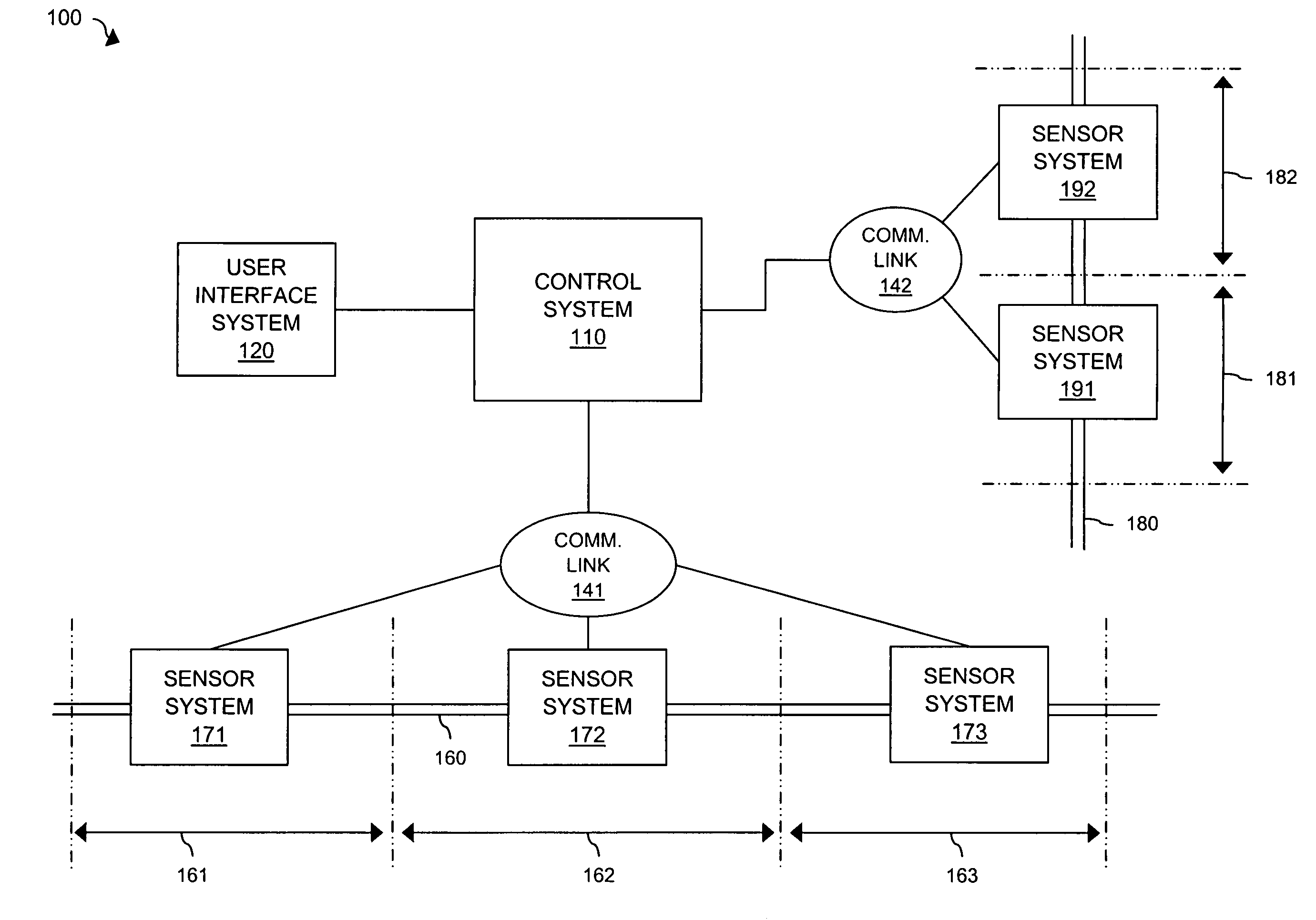
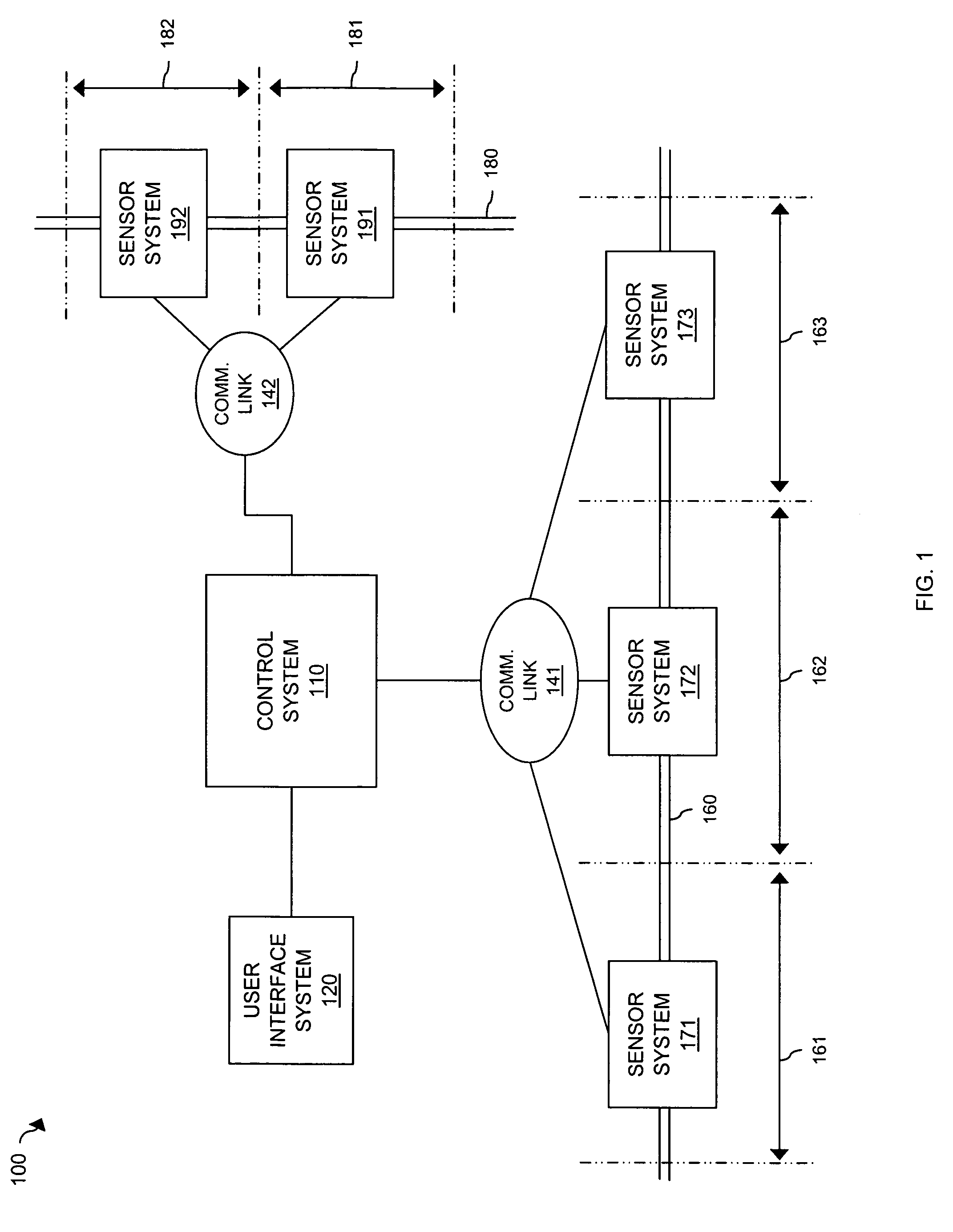
[0031]FIG. 1 illustrates perimeter security network 100 in an embodiment of the invention. Perimeter security network 100 includes control system 110, user interface system (UIS) 120, barrier 160, and barrier 180. Barrier 160 includes barrier segments 161, 162, and 163. Barrier 180 includes barrier segments 181 and 182. Sensor systems 171, 172, and 173 are coupled to barrier segments 161, 162, and 163 respectively. Sensor systems 191 and 192 are coupled to barrier segments 191 and 192 respectively. Sensor systems 171, 172, and 173 are in communication with control system 110 over communication link 141. Sensor systems 191 and 192 are in communication with control system 110 over communication link 142. It should be understood that, while illustrated as separate communication links, communication links 141 and 142 could comprise a single communication link.

[0032]Sensor systems 171-173 and 191-192 could be any sensor systems capable of performing re...

second embodiment

Configuration and Operation

FIGS. 4-7

[0045]FIG. 4 illustrates perimeter security network 400 in an embodiment of the invention. Perimeter security network 400 includes control system 410, user interface system (UIS) 420, mobile UIS 430, barrier 460, barrier 480, and weather station 435. Barrier 460 includes barrier segments 461, 462, and 463. Barrier 480 includes barrier segments 481 and 482. Sensor systems 471, 472, and 473 are coupled to barrier segments 461, 462, and 463 respectively. Sensor systems 491 and 492 are coupled to barrier segments 491 and 492 respectively. Sensor systems 471, 472, and 473 are in communication with control system 410 over communication link 441. Sensor systems 491 and 492 are in communication with control system 410 over communication link 442. It should be understood that, while illustrated as separate communication links, communication links 441 and 442 could comprise a single communication link.

[0046]Sensor systems 471-473 and 491-492 could be any se...


PUM


Abstract

A sensor system for monitoring a perimeter for a plurality of events comprises a signal sensor configured to receive an event signal for an event of the plurality of events, a processing system configured to process the event signal to determine if the event is a threat, confirm that the event is a threat in response to determining that the event is a threat, and generate a threat message identifying the event in response to confirming the threat, and an interface system configured to transmit the threat message.

Description

RELATED APPLICATIONS[0001]Not applicableFEDERALLY SPONSORED RESEARCH OR DEVELOPMENT[0002]Not applicableMICROFICHE APPENDIX[0003]Not applicableBACKGROUND OF THE INVENTION[0004]1. Field of the Invention[0005]The field of the invention relates to perimeter security networks, and in particular, to processing event signals to evaluate threat events.[0006]2. Description of the Prior Art[0007]Recently, many enterprises have become increasingly concerned with the issue of perimeter security. For example, military, municipal, and corporate enterprises desire to secure the perimeters of a wide variety of installations, such as airports, military bases, and corporate campuses.[0008]Typically, perimeter security systems are arranged with multiple sensors arrayed along a boundary and in communication with a central control system. Often times, the sensors are mounted on a barrier, such a fence. In general, the sensors monitor the boundary for event signals, such as vibration and heat signals. Up...

Claims


Application Information

Patent Timeline
IPC IPC(8): G08B13/00
CPCG08B13/122G08B29/188
Inventor DOYLE, ALAN T.HAY, ALAN C.
Owner ALLISON SYST
Why Eureka
Try Eureka