
VLAN router with firewall supporting multiple security layers

a firewall and router technology, applied in the field of firewalls, can solve the problems of inability to reduce the number of firewalls the router/firewall is expensive and time-consuming to install, configure, test and maintain, and the firewalls cannot be reduced using prior art firewalls, so as to reduce the comparison time and eliminate the redundant rules

Inactive Publication Date: 2008-11-11
TREND MICRO INC
View PDF19 Cites 19 Cited by
  • Summary
  • Abstract
  • Description
  • Claims
  • Application Information

AI Technical Summary

Benefits of technology

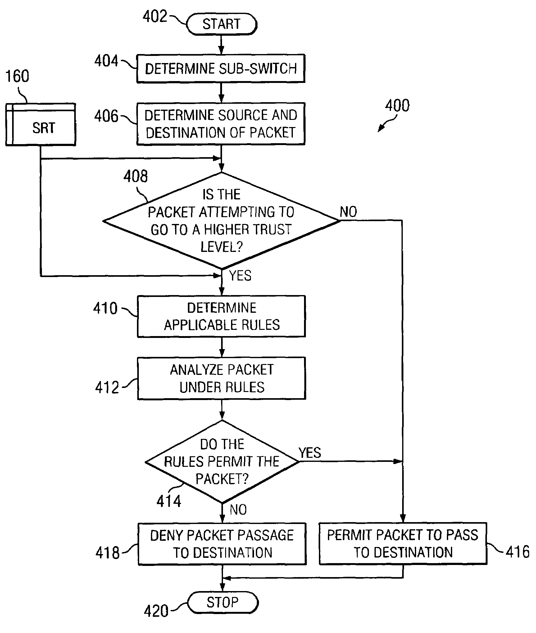
The present invention is a router with a firewall that can support different security levels. It creates multiple virtual local area networks (VLANs) using a network switch. The firewall includes a processor and memory with a configuration program and a security program. The firewall analyzes each packet and determines if it is allowed based on the rules and trust levels set by the administrator. The invention also divides the switch into sub-switches to reduce the comparison time and the time the packet stays in the firewall. Overall, the invention allows for a single firewall to be used for multiple firewalls and increases efficiency and security.

Problems solved by technology

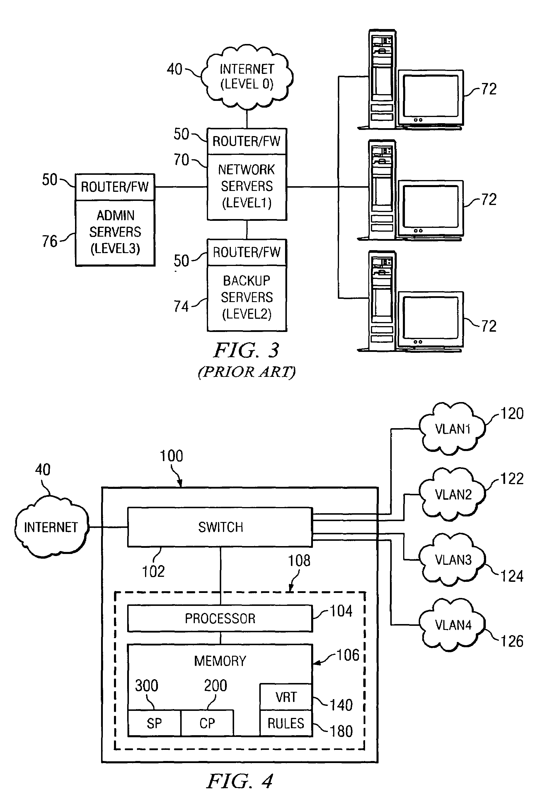
One of the problems with the computer network configuration depicted in FIG. 3 is that each router / firewall is expensive and time consuming to install, configure, test, and maintain.
The number of firewalls cannot be reduced using the prior art firewalls because the prior art firewalls do not allow the network administrator to use a single firewall to create multiple security levels.
The prior art firewalls are limited in that an individual firewall is needed for each security boundary.
Even with the prior art routers supporting multiple computer networks, the firewall within the router is not able to create different security levels within the individual computer networks.

Method used


Image

  • VLAN router with firewall supporting multiple security layers
  • VLAN router with firewall supporting multiple security layers
  • VLAN router with firewall supporting multiple security layers

Examples


Embodiment Construction

[0024]As used herein, the term “analyze” shall mean to compare a packet to a list of rules associated with a trust level and determine if the rules permit or deny the packet.

[0025]As used herein, the term “computer” shall mean a machine having a processor, a memory, and an operating system, capable of interaction with a user or other computer, and shall include without limitation desktop computers, notebook computers, personal digital assistants (PDAs), servers, handheld computers, and similar devices.

[0026]As used herein, the term “deny” shall mean to block transmission of a packet from a source to a destination at a firewall.

[0027]As used herein, the term “firewall” shall mean a system or device that enforces a security boundary between two or more computers or computer networks.

[0028]As used herein, the term “packet” shall mean a discrete quantity of data transmitted from a source to a destination.

[0029]As used herein, the term “permit” shall mean to allow transmission of a packe...


PUM


Abstract

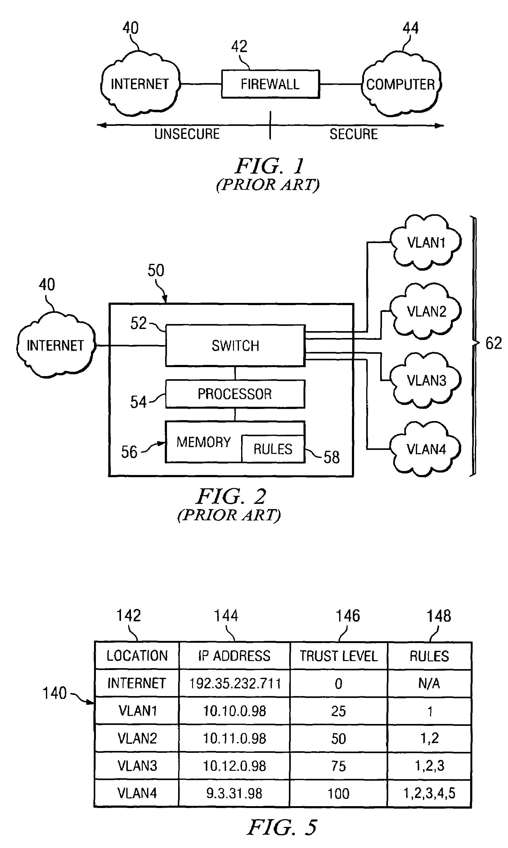
A router containing a firewall capable of supporting a plurality of different security levels. The router of the present invention creates a plurality of Virtual Local Area Networks (VLANs) using a network switch. The VLAN Rules Table (VRT) allows a network administrator to designate a trust level for each VLAN. The trust level may be different for every VLAN and the administrator may designate different rules for each VLAN. The Security Program (SP) analyzes each packet passing through the firewall and determines if the packet is permitted under the rules for the VLAN trust level. An alterative embodiment in which the switch in the router is divided into a plurality of sub-switches is also disclosed. In the alternative embodiment, the firewall need only compare the packet to rules which were not applied in the lower trust levels, eliminating the redundant rules from the comparison process.

Description

FIELD OF THE INVENTION[0001]The present invention is directed generally to a security apparatus for a computer network and specifically to a firewall for a plurality of networks with different security levels.BACKGROUND OF THE INVENTION[0002]A packet is a discrete amount of data transmitted between computers. Packets are transmitted from one computer to another computer using a protocol. Transmission Control Protocol (TCP) is a common protocol and governs the breakup, transmission, reassembly, and verification of the complete messages from one computer to another via Internet Protocol (IP) addresses. Many other types of protocols exist including Simple Mail Transfer Protocol (SMTP), Point to Point Protocol (PPP), Internet Control Message Protocol (ICMP), and User Datagram Protocol (UDP). Packets contain a header containing the IP source address, the IP destination address, the type of protocol (i.e. TCP, UDP, or ICMP), the TCP or UDP source port, the TCP or UDP destination port, and...

Claims


Application Information

Patent Timeline
Patent Type & Authority Patents(United States)
IPC IPC(8): H04L9/32G06F17/00H04L9/00H04L29/06
CPCH04L63/0236H04L63/105
Inventor CHANG, KYUSUNMIMS, JOHN ALANWILSON, ALLEN KEITH
Owner TREND MICRO INC
Learn More