Turbine blade including revised trailing edge cooling

a turbine blade and cooling circuit technology, applied in the direction of machines/engines, sustainable transportation, mechanical equipment, etc., can solve the problems of increased stress within the turbine blade, non-uniform airflow through the feed passage, and extreme harsh environment operation, so as to reduce airflow, maximize cooling efficiency, and maximize cooling efficiency

Active Publication Date: 2008-11-18
RTX CORP
View PDF5 Cites 19 Cited by
  • Summary
  • Abstract
  • Description
  • Claims
  • Application Information

AI Technical Summary

Benefits of technology

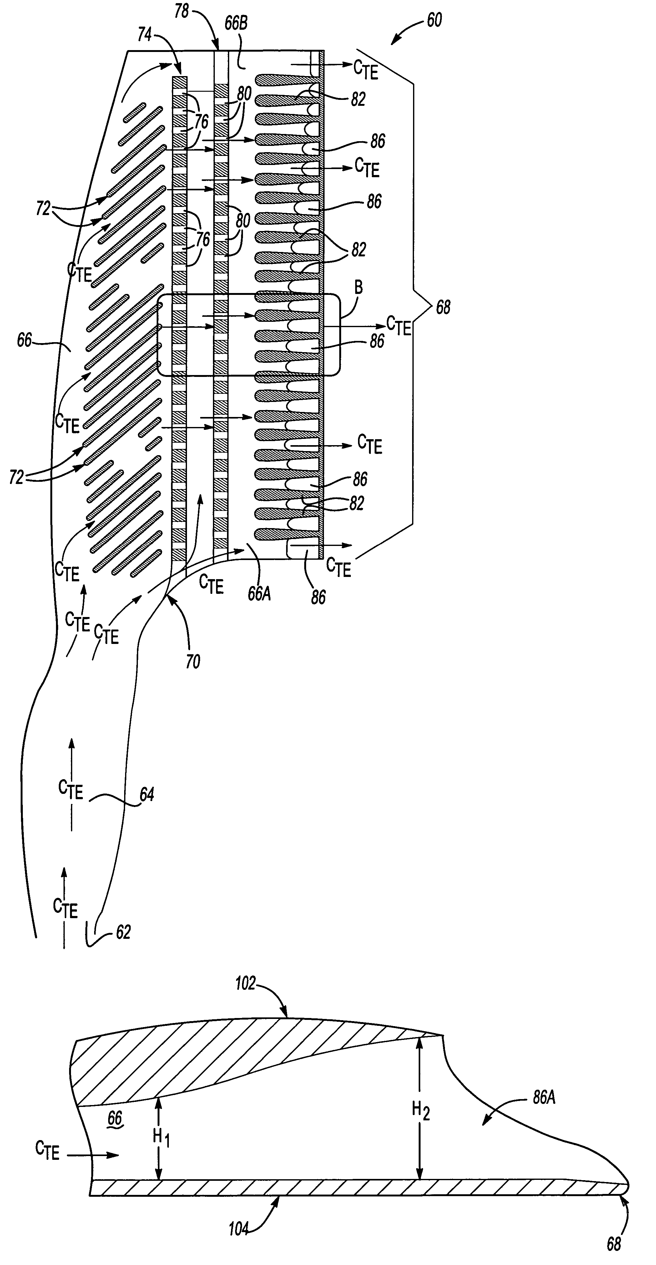
[0013]The feed passage includes at least one barrier with cross-over holes optimized to maximize cooling efficiency and reduce an airflow. Further, the geometry and positioning of both the cross-over holes and teardrop shaped protrusions downstream of the cross-over holes have been optimized to maximize cooling efficiency and reduce airflow.
[0014]An improved transition between the inlet passage and the feed passage is also provided. The improved transition is arcuate, allowing the airflow to maintain attachment to an inside wall of the cooling circuit and flow unimpeded from the inlet passage to the feed passage. This prevents airflow starvation within a lower portion of the feed cavity and the trailing edge.
[0015]Finally, the geometry of the pockets disposed along the trailing edge has been optimized to improve cooling.

Problems solved by technology

Further, because the turbine blades are located downstream of the combustor where fuel and air are mixed and burned, they are required to operate in an extremely harsh environment.
As the hot burnt fuel-air mixture travels past the leading edge, along the pressure side, and past the trailing edge, a temperature associated with the individual turbine blades increases resulting in increased stress within the turbine blade.
This variation in size and position of the cross-over holes can cause a non-uniform airflow through the feed passage.
This may result in additional hot spots, i.e. areas of higher stress, within the turbine blade.
Further, known positioning of the cross-over holes in relation to the teardrop shaped protrusions may also have a detrimental effect on the cooling efficiency of the airflow.

Method used


Image

  • Turbine blade including revised trailing edge cooling
  • Turbine blade including revised trailing edge cooling
  • Turbine blade including revised trailing edge cooling

Examples


Embodiment Construction

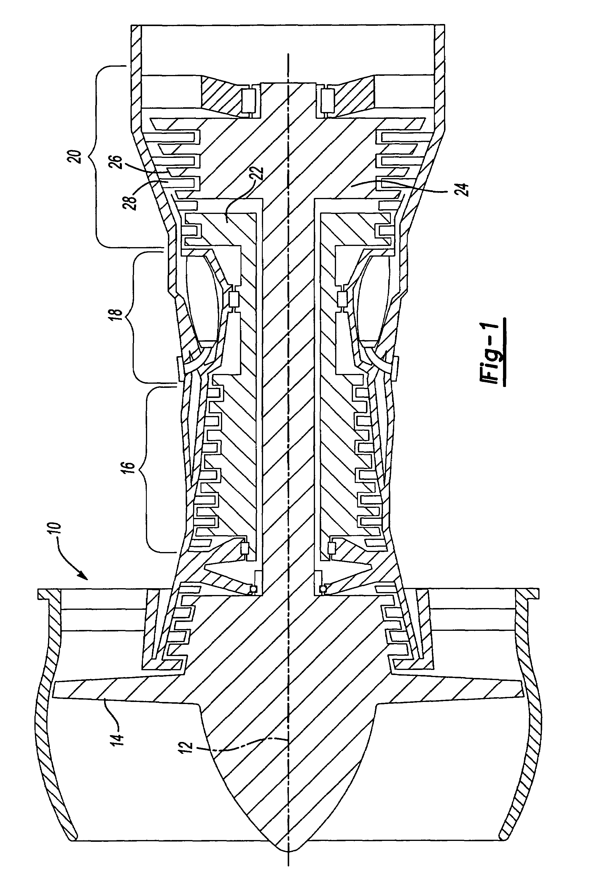
[0027]FIG. 1 is a schematic illustration of an example gas turbine engine 10 circumferentially disposed about an engine centerline, or axial centerline axis 12. The example gas turbine engine 10 includes a fan 14, a compressor 16, a combustor 18, and a turbine assembly 20. As is known, intake air from the fan 14 is compressed in the compressor 16. The compressed air is mixed with fuel and burned in the combustor 18 and expanded in the turbine assembly 20. The turbine assembly 20 includes rotors 22 and 24 that, in response to the expansion, rotate, driving the compressor 16 and the fan 14. The turbine assembly 20 includes alternating rows of rotary blades 26 and static airfoils or vanes 28, which are mounted to the rotors 22 and 24. The example gas turbine engine 10 may, for example, be a gas turbine used for power generation or propulsion. However, this is not a limitation on the present invention, which may be employed on gas turbines used for electrical power generation, in aircra...


PUM


Abstract

The present invention provides an improved cooling circuit for a trailing edge of a turbine blade. The cooling circuit includes an inlet passage that receives a airflow and distributes the airflow through a feed passage. The feed passage primarily includes trip strips, at least one barrier including cross-over holes, teardrop shaped protrusions, and pockets disposed along a trailing edge. The geometry and positioning of both the cross-over holes and teardrop shaped protrusions downstream of the cross-over holes have been optimized to maximize cooling efficiency and reduce airflow. An improved transition between the inlet passage and the feed passage is also provided, which is arcuate and allows the airflow to maintain attachment and flow unimpeded from the inlet passage to the feed passage. The geometry of the pockets disposed along the trailing edge is optimized to improve cooling.

Description

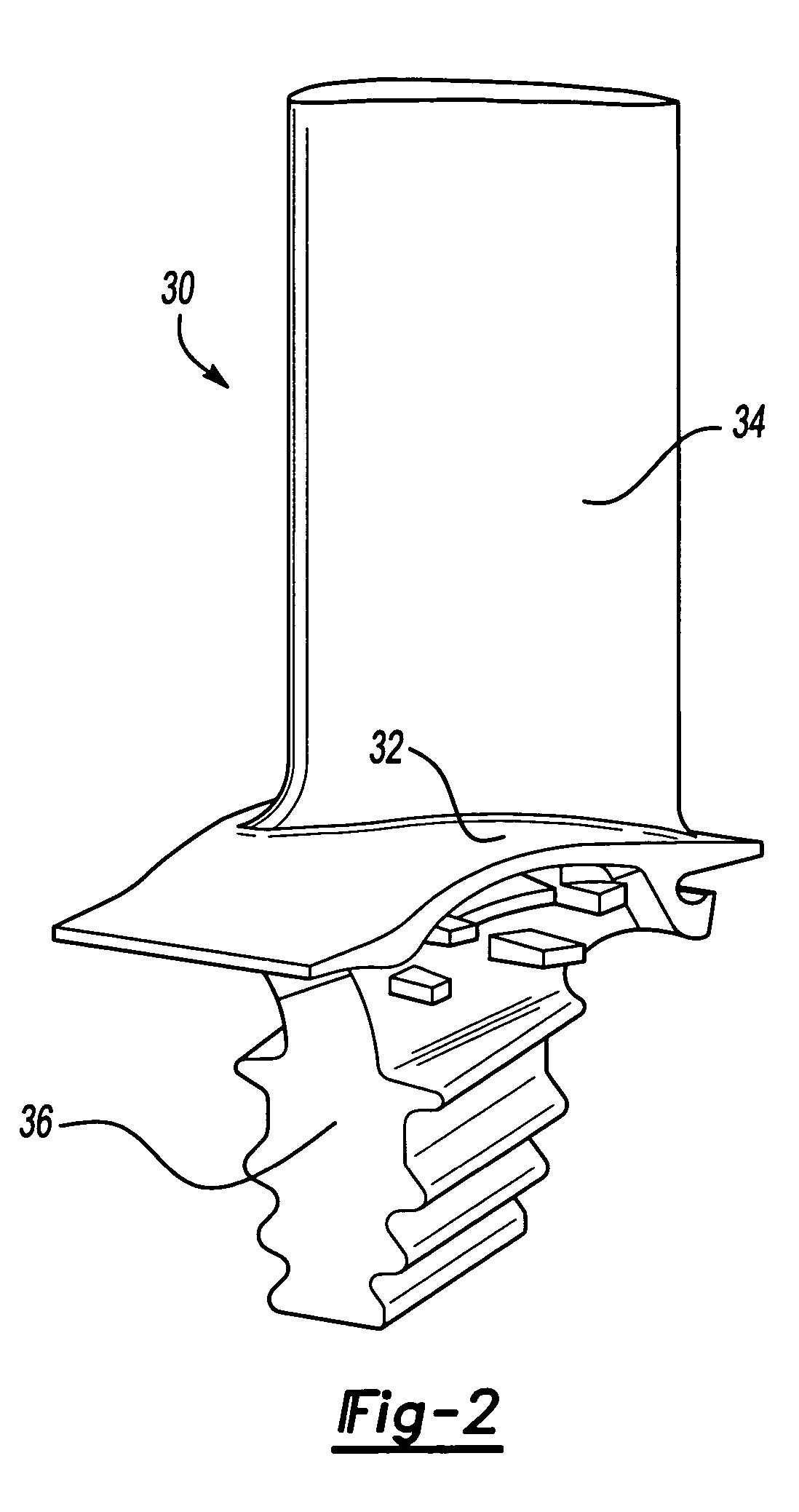
BACKGROUND OF THE INVENTION[0001]This application relates generally to gas turbine engines and more specifically to a cooled turbine blade having a trailing edge cooling circuit with several unique features.[0002]Conventional gas turbine engines include a compressor, a combustor and a turbine assembly that has a plurality of adjacent turbine blades disposed about a circumference of a turbine rotor. Each turbine blade typically includes a root that attaches to the rotor, a platform and an airfoil that extends radially outwardly from the rotor.[0003]The compressor receives intake air. The intake air is compressed by the compressor and delivered primarily to the combustor where the compressed air and fuel are mixed and burned. A portion of the compressed air is bled from the compressor and fed to the turbine to cool the turbine blades.[0004]The turbine blades are used to provide power in turbo machines by exerting a torque on a shaft that is rotating at a high speed. As such, the turbi...

Claims


Application Information

Patent Timeline
Patent Type & Authority Patents(United States)
IPC IPC(8): F01D5/18
CPCF01D5/187Y02T50/676F05D2260/2212F05D2260/22141Y02T50/60
Inventor CHARBONNEAU, ROBERT A.BOTTICELLO, KENNETH P.GREGG, SHAWN J.HLAVATY, KIRK DAVIDLEVINE, JEFFREY R.LONCZAK, KENNETH A.MCGARRAH, CRAIG R.MONGILLO, DOMINIC J.O'NEILL, LISA P.PIETRASZKIEWICZ, EDWARDSALZILLO, RICHARD M.TERRY, HEATHER ANN
Owner RTX CORP
Why Eureka
Try Eureka