
Pre-stretched tie-bolt for use in a gas turbine engine and method

a technology for gas turbine engines and prestretched nut nuts, which is applied in the direction of propellers, propulsive elements, water-acting propulsive elements, etc., can solve the problem that the final position of the nut will not necessarily be exactly

Inactive Publication Date: 2008-11-18
PRATT & WHITNEY CANADA CORP
View PDF23 Cites 27 Cited by
  • Summary
  • Abstract
  • Description
  • Claims
  • Application Information

AI Technical Summary

Benefits of technology

The present invention provides a tie-bolt for securing a component in a gas turbine engine. The tie-bolt has an elongated tubular portion, a retaining portion, and an annular spacer. The tie-bolt can be easily mounted to a main shaft and can provide a secure and reliable attachment for components in the engine. The technical effects of the invention include improved attachment reliability and reduced assembly time and cost.

Problems solved by technology

The problem is that the final position of the nut will not necessarily be exactly the same from one engine to other due to various factors.

Method used


Image

  • Pre-stretched tie-bolt for use in a gas turbine engine and method
  • Pre-stretched tie-bolt for use in a gas turbine engine and method
  • Pre-stretched tie-bolt for use in a gas turbine engine and method

Examples


Embodiment Construction

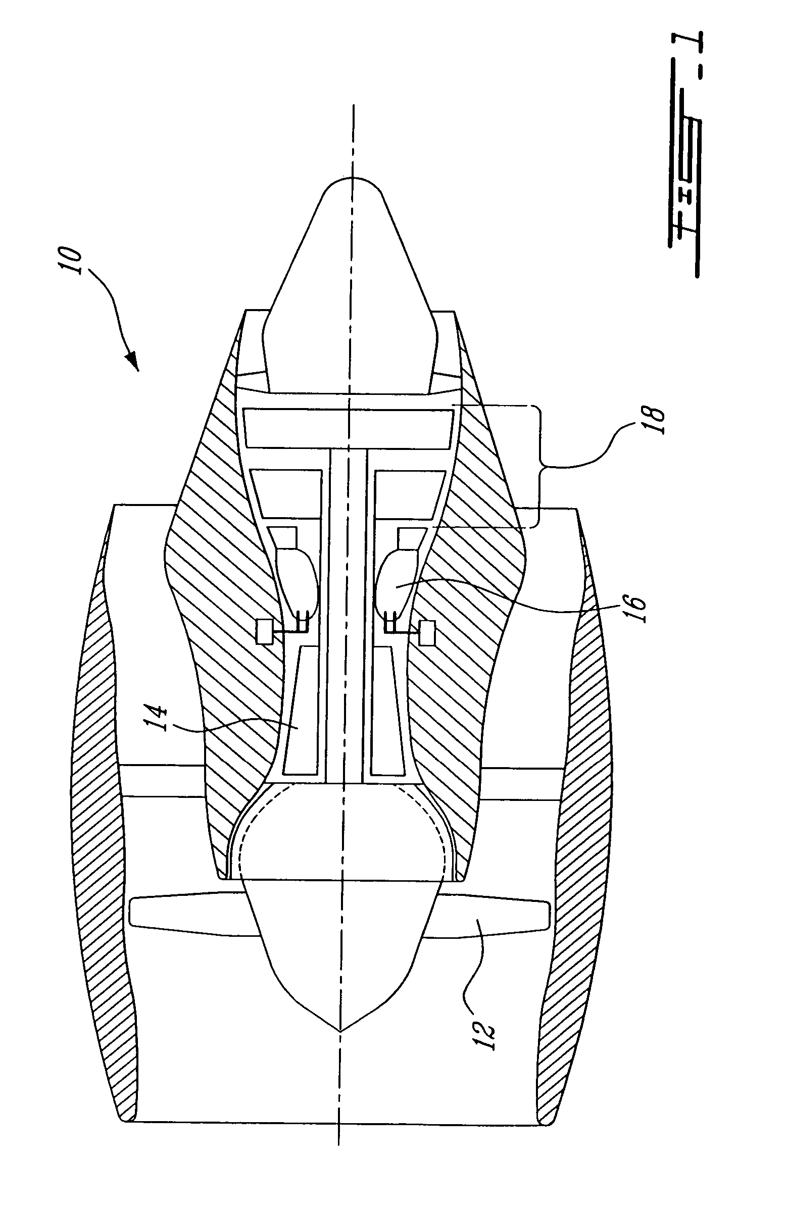
[0013]FIG. 1 illustrates a gas turbine engine 10 of a type preferably provided for use in subsonic flight, generally comprising in serial flow communication a fan 12 through which ambient air is propelled, a multistage compressor 14 for pressurizing the air, a combustor 16 in which the compressed air is mixed with fuel and ignited for generating an annular stream of hot combustion gases, and a turbine section 18 for extracting energy from the combustion gases.

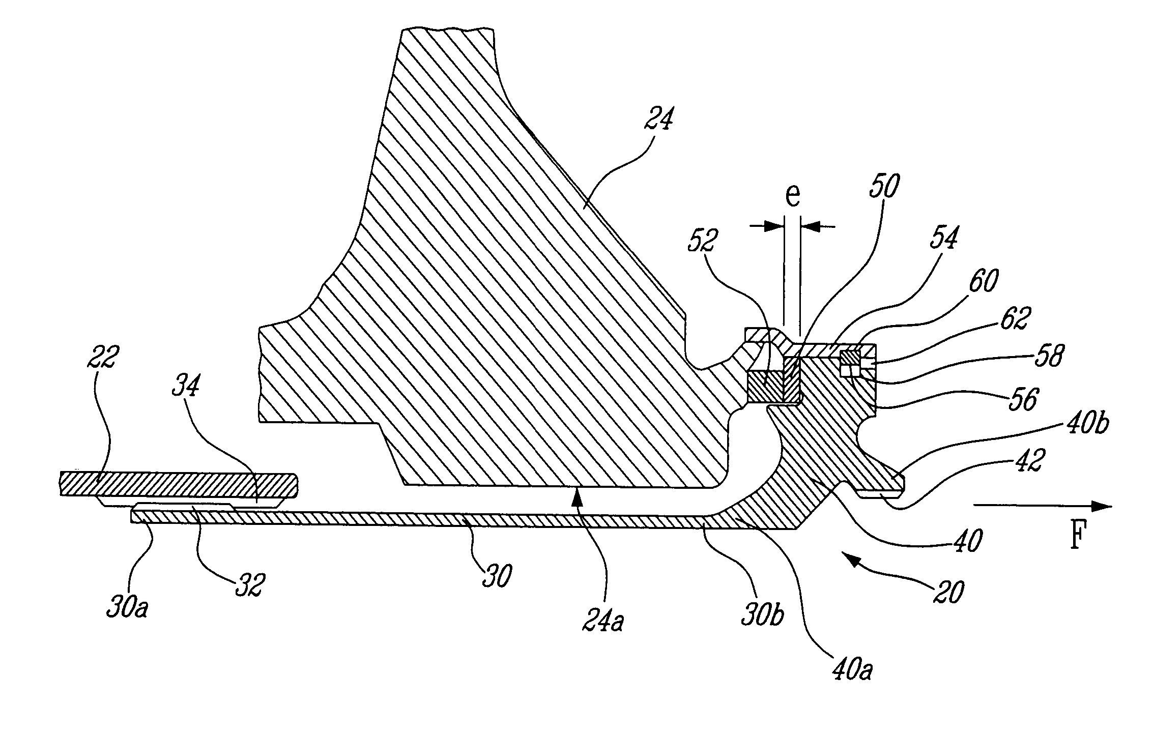
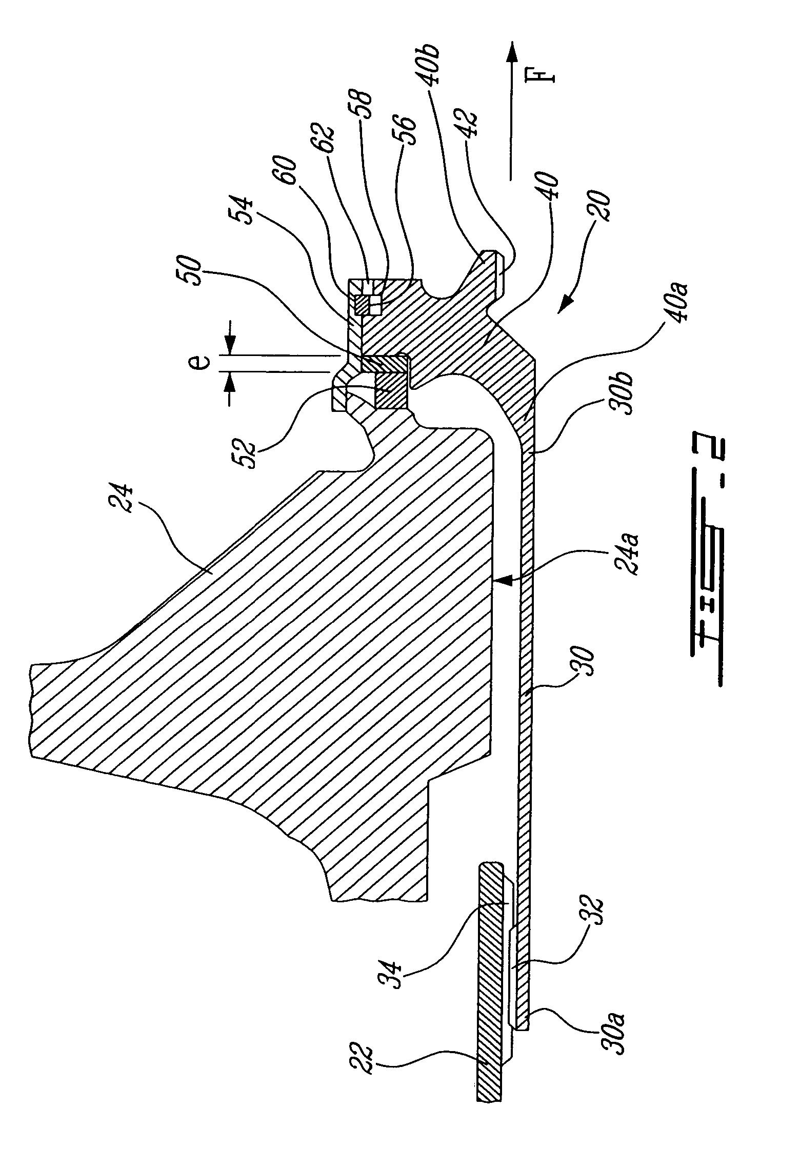
[0014]FIG. 2 shows an example of a tie-bolt 20 in accordance a possible embodiment. This tie-bolt 20 is designed to secure one or more components at the end of a main shaft 22. These components include one or more discs that are part of a turbine rotor or a compressor rotor. Other kinds of components can also be secured to the main shaft 22 by the tie-bolt 20. In FIG. 2, the tie-bolt 20 retains a rotor disc 24.

[0015]The tie-bolt 20 comprises an elongated tubular portion 30 having two opposite ends 30a, 30b. The first end 30a is...


PUM


Abstract

The tie-bolt comprises an elongated tubular portion and a retaining portion coaxially and rigidly attached to the tubular portion. The retaining portion has an outer diameter larger than that of the tubular portion. An annular spacer is removably provided between the retaining portion and the component to be secured by the tie-bolt.

Description

TECHNICAL FIELD[0001]The field of invention relates generally to the design of a pre-stretched tie-bolt for use in gas turbine engines and, more particularly, to an improved tie-bolt and a method of mounting the same.BACKGROUND OF THE ART[0002]A tie-bolt is used in a gas turbine engine to secure some of the components mounted around a shaft. The tie-bolt is coaxially mounted at the end of the shaft.[0003]The tie-bolts are initially pre-stretched when mounted in a gas turbine engine. The pre-stretching ensures a very strong hold of the component or components to be retained and is required to compensate for the thermal expansion of the tie-bolt due to the surrounding heated environment.[0004]Traditionally, the pre-stretching requires that a nut be positioned by hand along the tie-shaft while the tie-bolt is pulled using an hydraulic actuator. The nut is rotated until it abuts the component to be held. The problem is that the final position of the nut will not necessarily be exactly t...

Claims


Application Information

Patent Timeline
Patent Type & Authority Patents(United States)
IPC IPC(8): B64C11/04
CPCF01D5/066F05B2260/301
Inventor BOUCHARD, GUY
Owner PRATT & WHITNEY CANADA CORP
Learn More