Power and safety control hub

a power and safety control and hub technology, applied in the direction of emergency protective circuit arrangements, emergency protection circuit arrangements, relays, etc., can solve the problems of no device that, when used with connected networked controls, automatically brings to a halt any connected mechanical drive, etc., to reduce engineering effort, reduce time necessary, and ease wiring requirements

Active Publication Date: 2008-11-18
TEKNIC
View PDF28 Cites 17 Cited by
  • Summary
  • Abstract
  • Description
  • Claims
  • Application Information

AI Technical Summary

Benefits of technology

[0016]Our invention represents a significant advance in its field. It reduces engineering effort significantly, substantially reducing the time necessary to bring a system to market. It eases wiring requirements, lowering total machine costs. It also integrates numerous functions in one compact enclosure, supporting a smaller machine footprint. Finally, it speeds compliance inspection and testing of a machine for: EMC (electromagnetic compatibility); Machine Safety (mechanical hazards); and Electrical Safety (shock and fire hazards). It accomplishes these goals via several important innovations, as further outlined below.
[0020]Fourth, our invention integrates segmented hazardous power control (load / unload and main machine / equipment areas) so that the main area can be operating while the load / unload area has power disconnected. It thereby allows the main area of the machine to operate while an area of the machine used for the loading and unloading of work in and out of the machine by a human operator is rendered safe. This increases the machine's effective throughput in a manufacturing plant.
[0022]Sixth, our power and safety control hub also includes a safety control and monitoring algorithm that automatically forces the test on e-stop switches and interlocks in a machine each time the machine is powered up (or reset). It avoids having to depend upon a voluntary or externally enforced manual procedure by forcing the operator to perform a test cycle for e-stops and interlocks before hazardous power can be applied, each time the machine is powered up (or upon a reset of the power and safety control hub from the host control software).
[0023]Seventh, it has a state driven safety control and monitoring algorithm that pinpoints at least one of wiring and device problems for rapid debug. This software algorithm stores in memory the last sequence of switching states which, once an error occurs, can easily be decoded to isolate a small fraction of the fault tree that could have caused that error. This makes debugging of the system in the case of a safety fault much easier.
[0024]Eighth, it includes internal self-protection that automatically forces a control safety power disconnect (after warning the host) if the unit should approach its maximum operating temperature, or if a cooling fan slows or stops. This feature specifically safeguards hazardous power disconnect devices and control circuits by forcing a safety shutdown—removing hazardous power before the temperature is elevated to a level that could cause unreliable operation of the safety control system. As such, this is an additional safeguard enhancing the functional reliability of the machinery safety system.
[0025]Ninth, our power and safety control hub for overall power control, safety control and power distribution incorporates safety monitoring software for the synchronous de-bouncing of the interlocks and e-stop switch inputs (as a vector) to eliminate false trips. Unlike former systems using electronic circuits or software, our system uses a software algorithm constructed to de-bounce switches when several switches must be monitored for simultaneous operation. In further contrast to prior art, our software processes the switch inputs as a vector, a binary number formed by the concatenation of the individual switch states.

Problems solved by technology

There is currently no device that constitutes a power and safety control hub for power control, safety control, and power distribution.
There is no product at present that integrates all of these functions into a single integrated system for use as a power and safety control hub for overall power control, safety control and power distribution in many different applications.
However, there is a need for a method for accomplishing these single fault tolerance and monitoring requirements without using either of these typically expensive techniques.
However, there is currently no device that, when used with connected networked controls, automatically brings to a halt any connected mechanical drives in the split second before it removes power.
Examples of equipment that operates in this way does exist, however, there are currently no integrated safety control products that accomplish this.
The stored charge in these capacitors constitutes a hazard until they are discharged.
However, there are currently no integrated safety control products that accomplish this.
However, there is nothing that avoids having to depend upon this type of relatively unreliable manual procedure for e-stop switches and interlocks.
However, there is currently no power and safety control hub for overall power control, safety control and power distribution that incorporates this feature.
When these switch signals are used by electronics, these transitions can confuse the circuits unless they are de-bounced.
However, traditional de-bouncing of individual contact inputs is insufficient for applications that need to monitor simultaneous switch operation.
This usually makes the software code complicated and harder to construct, test and debug.
Although visual blown indicators for individual over current devices are common, there are no examples of a single comprehensive indicator that provides a signal (by sounds or otherwise) when there is any blown fuse or tripped circuit breaker in the power distribution product.
These safety standards state that the resetting of the e-stop switch simply arms the hazardous power control circuits (necessary, but not sufficient for the reapplication of hazardous power).
There is, however, nothing that has a circuit that integrates the hazardous power reset switch function with the On-Off switch panel, allowing the On switch to double as the hazardous power reset switch.
However, there is currently no device in the field that contains a circuit that can be used to extend this shutdown action to the entire machine when the host computer shuts down.

Method used


Image

  • Power and safety control hub
  • Power and safety control hub
  • Power and safety control hub

Examples


Embodiment Construction

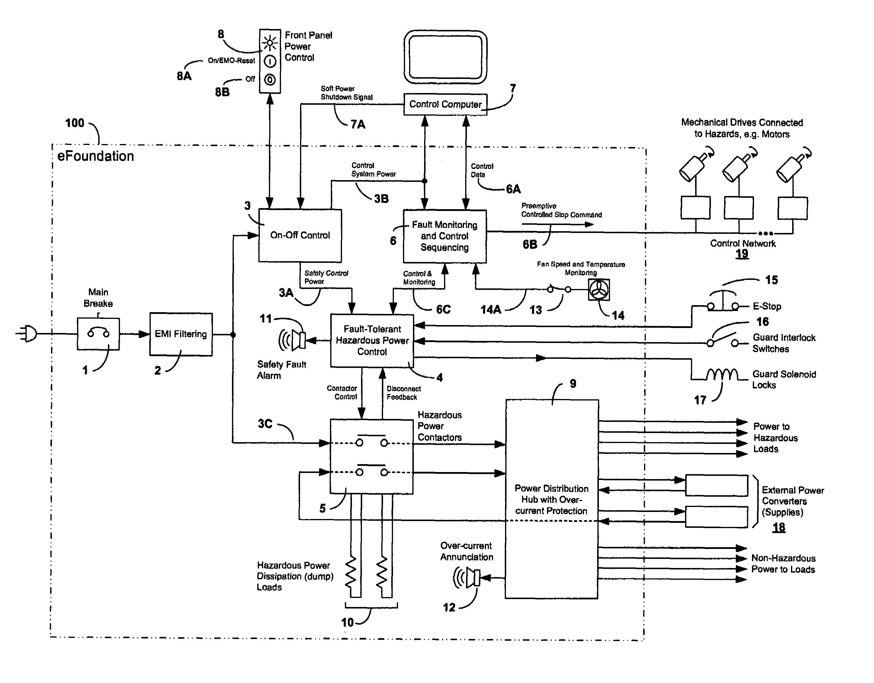
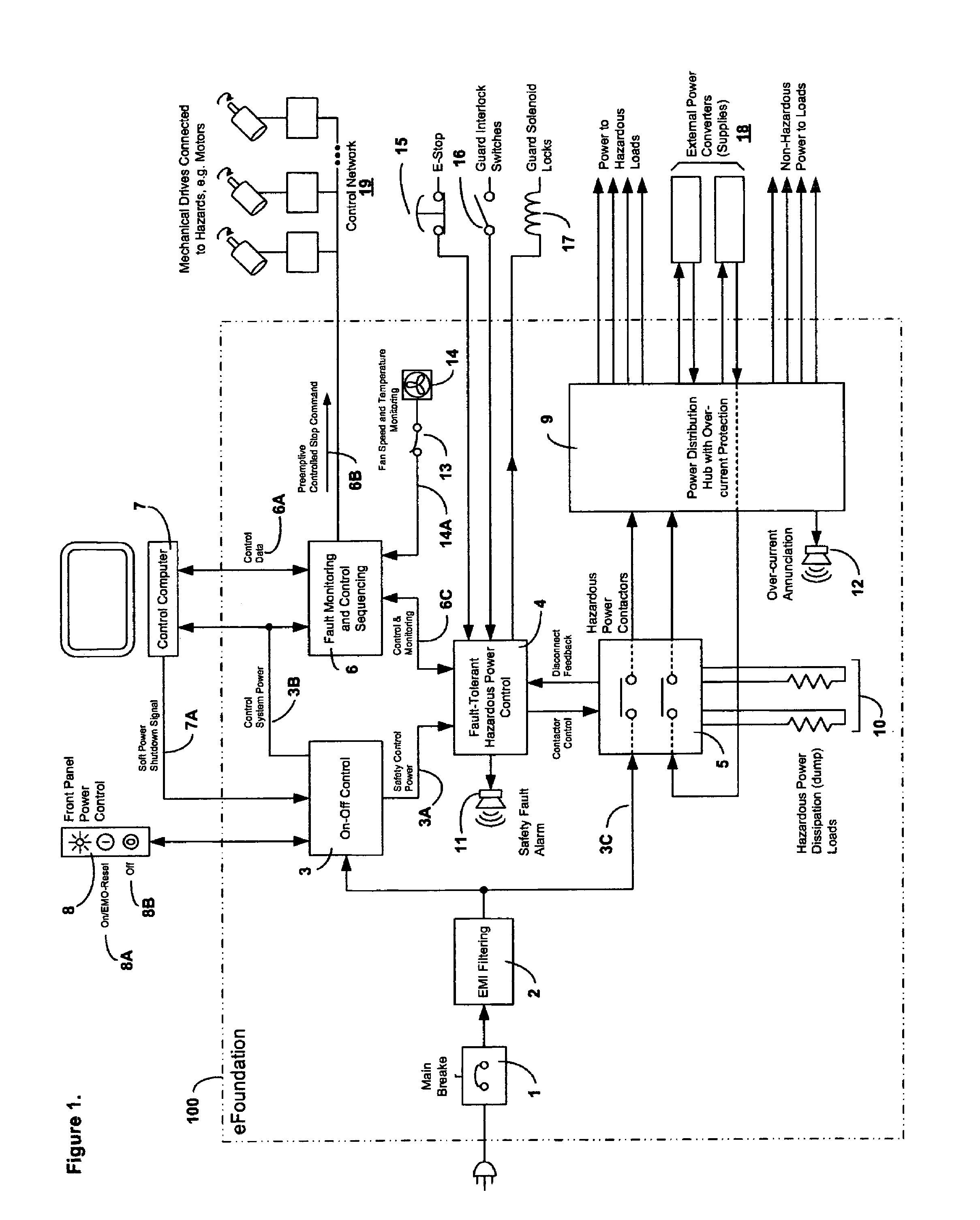
[0037]As previously noted, FIG. 1 provides an overview of our invention in the form of a schematic diagram showing power and control features of our power and safety control hub for power control, safety control, and power distribution (“control hub”100). As it is an overview, the workings, features, internal components, and interconnections between many of the elements illustrated in FIG. 1 will be discussed with greater particularity in subsequent sections. (As further discussed below, FIG. 1 also shows various ancillary devices connected to and / or controlled by control hub 100 that are not part of control hub 100).

[0038]Nonetheless, in passing, it should be noted that control hub 100 includes a main breaker 1 and EMI filtering 2 as well as on-off control 3, which is connected to fault tolerant hazardous power control system 4. Hazardous power control system 4 is, in turn, linked to hazardous power contactors 5 and fault monitoring and control sequencing system 6. Also shown are a...


PUM


Abstract

A power and safety control hub, integrating fault tolerant power disconnect control, software monitoring of disconnect and multi-voltage power distribution and disconnect with non-hazardous power control, EMI filtering and multi-circuit current protection in a single unit, coordinating shutdown of connected mechanical drives, commanding them to come to a controlled stop before safety power is disconnected. The hub may also integrates segmented hazardous power control and automatically discharge energy sources within connected mechanical drives at the time of safety power disconnect of hazardous power. The hub may also include internal self-protection that automatically forces a control safety power disconnect (after warning the host) if the unit should approach its maximum operating temperature, or if a cooling fan stops.

Description

BACKGROUND OF THE INVENTION[0001]1. Field of the Invention[0002]The invention pertains to the field of power control, safety, and distribution equipment. More particularly, the invention pertains to a power and safety control hub for power control, safety control, and power distribution.[0003]2. Description of Related Art[0004]There is currently no device that constitutes a power and safety control hub for power control, safety control, and power distribution. As part of its function, a power and safety control hub of this type should integrate fault tolerant power disconnect control, software monitoring of disconnect and multi-voltage power distribution and disconnect with non-hazardous power control, EMI filtering and multi-circuit current protection in a single unit. There are presently some products and machines that incorporate some or part of these functions, but this is done on a custom-made basis for each machine model. There is no product at present that integrates all of t...

Claims


Application Information

Patent Timeline
Patent Type & Authority Patents(United States)
IPC IPC(8): H02H7/00
CPCH02J13/0096H01H47/002H02H3/04H02J13/00036H02J13/0004H02J4/00H02J13/00002Y04S10/30Y02E60/00
Inventor BUCELLA, THOMAS JOHNBLOCK, JEREMY MICHAELFUCHS, DAVID EDWARDTESTA, FRANCIS JOSEPHSEWHUK, DAVID WILLIAMLARSON, DAVID ROGER
Owner TEKNIC
Why Eureka
Try Eureka