Magnetic random access memory with improved data reading method

a random access and data technology, applied in the field of magnetic random access memory, can solve the problem of greatly impaired reliability of read operation, and achieve the effect of high reliability

Active Publication Date: 2008-11-18
NEC CORP
View PDF11 Cites 73 Cited by
  • Summary
  • Abstract
  • Description
  • Claims
  • Application Information

AI Technical Summary

Benefits of technology

[0020]Therefore, it is an object of the present invention to provide a magnetic random access memory (MRAM) that can determine a data stored in a memory cell of the MRAM at a high reliability.
[0021]Another object of the present invention is to provide a magnetic random access memory (MRAM) that can read out a data stored in a memory cell of the MRAM at a high reliability while restraining increase of a chip area.
[0022]Still another object of the present invention is to provide a magnetic random access memory (MRAM) that can read out a data stored in a memory cell of the MRAM at a high reliability without depending on a resistance value and MR ratio of a TMR.
[0024]Another object of the present invention is to provide a magnetic random access memory (MRAM) in which a voltage to be applied between the both ends of a TMR used in a reference cell and other circuits is substantially equal to a voltage to be applied between the both ends of a TMR used in a memory cell so that it is possible to prevent a read reliability from decreasing due to bias dependency peculiar to the TMR.

Problems solved by technology

When the shit is present in the TMR resistance value, there is a possibility that the reliability in the read operation is greatly impaired.

Method used


Image

  • Magnetic random access memory with improved data reading method
  • Magnetic random access memory with improved data reading method
  • Magnetic random access memory with improved data reading method

Examples


first embodiment

[0071]First, the configuration of the magnetic random access memory according to the first embodiment of the present invention will be described below.

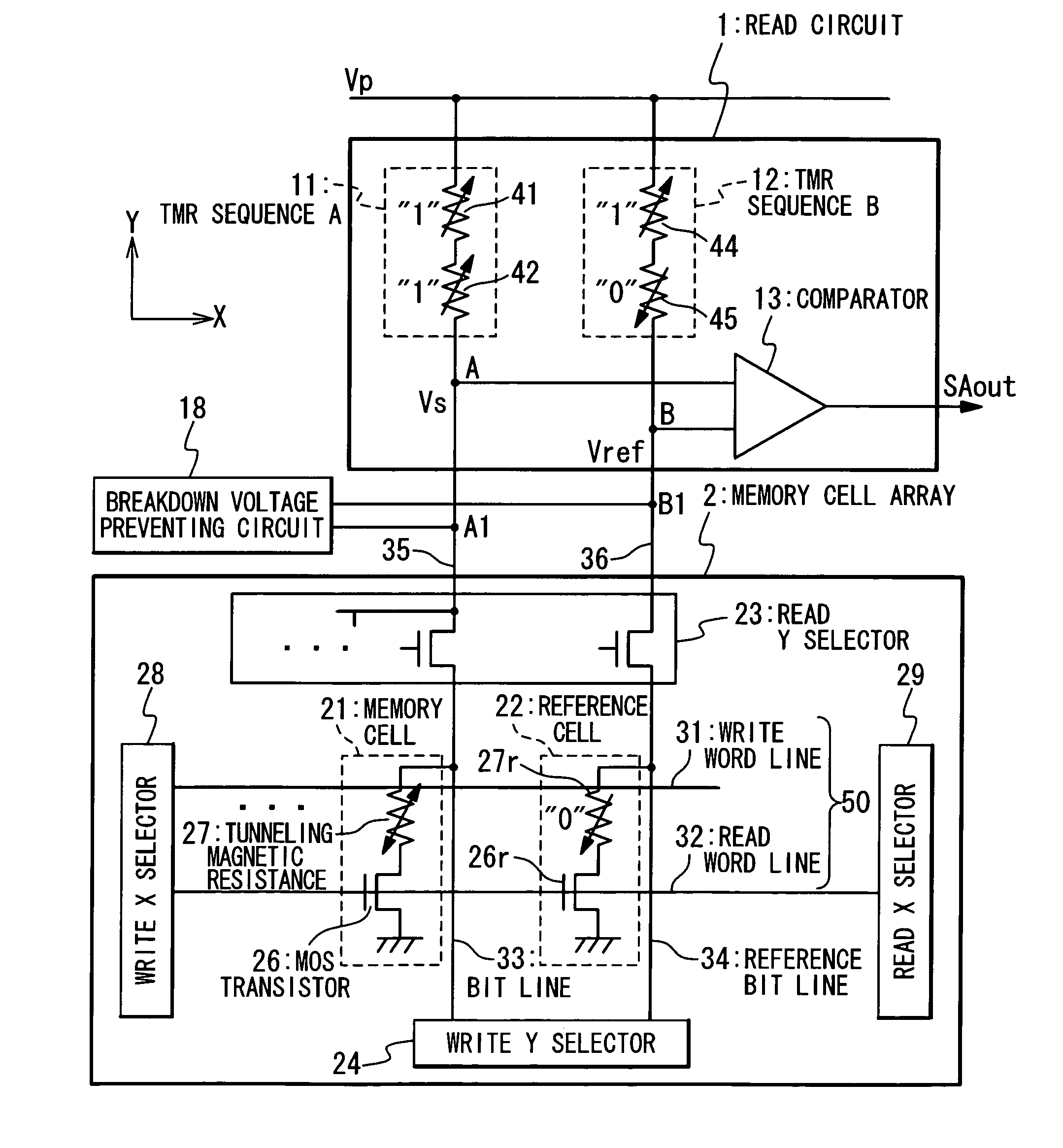
[0072]FIG. 4 is a block diagram showing the magnetic random access memory according to the first embodiment of the present invention. The magnetic random access memory includes a read circuit 1, a memory cell array 2, and a breakdown voltage preventing circuit 18.

[0073]The memory cell array 2 stores data in a nonvolatile state by a memory cell 21 having a spontaneous magnetization whose direction can be freely reversed. The memory cell array 2 includes a plurality of memory cells 21, a plurality of reference cells (reference memory cells) 22, a plurality of bit lines 33, a reference bit line 34, a plurality of pairs of word lines 50, a read Y selector 23, a write Y selector 24, a write X selector 28, and a read X selector 29.

[0074]The bit lines 33 extend in Y direction as a first direction. One end of the bit line 33 is connected to t...

second embodiment

[0107]Next, the magnetic random access memory according to the second embodiment of the present invention will be described below.

[0108]First, the configuration of the magnetic random access memory according to the second embodiment of the present invention will be described below.

[0109]FIG. 9 is a block diagram of the magnetic random access memory according to the second embodiment of the present invention. This embodiment is different from the first embodiment (FIG. 4) in that the TMR sequence A 11 is changed to a TMR sequence C 11a and data of “1” is always stored in the reference cell 22. The TMR sequence C 11a always stores the data of “0”, showing that a TMR is kept in a parallel state in each of the tunneling magnetic resistances 41 and 42. A TMR sequence B 12a is the same as the TMR sequence B 12 and other components in FIG. 9 are the same as those of the first embodiment (FIG. 4). Therefore, their description is omitted.

[0110]Because the operation of the magnetic random acc...

third embodiment

[0114]Next, the magnetic random access memory according to the third embodiment of the present invention will be described below.

[0115]First, the configuration of the magnetic random access memory according to the third embodiment of the present invention will be described.

[0116]FIG. 11 is a block diagram showing the configuration of the magnetic random access memory according to the third embodiment of the present invention. The configuration is different from the configuration shown in FIG. 4 in the following point in a read circuit 1b. That is, a plurality of sets are present, in each of which a TMR sequence A 11-i (i=1−n: natural number) and a switch 14-i (i=1−n: natural number) are connected in series. The plurality of sets are connected each other in parallel. Moreover, one end of each of the plurality of sets is connected to the wiring 35 and the other end of it is connected to the first power supply (Vp). Similarly, the plurality of sets are present in each of which a TMR se...


PUM


Abstract

An MRAM has a plurality of bit lines, a reference bit line, a plurality of memory cells and reference cells and a read section. The memory cells are provided along the bit lines and the reference cells along the reference bit line. The memory cell and reference cell have a tunneling magnetic resistance and a reference tunneling magnetic resistance, each of which has a spontaneous magnetization whose direction is reversed in accordance with data stored therein. The read section has a first resistance section which contains a ninth terminal connected with a bit line and a tenth terminal connected with the first power supply, a second resistance section which contains an eleventh terminal connected with the reference bit line and a twelfth terminal connected with the first power supply, and a comparing section which compares a sense voltage on the ninth terminal and a reference voltage of the eleventh terminal.

Description

TECHNICAL FIELD[0001]The present invention relates to a magnetic random access memory, particularly to a magnetic random access memory with a data reading method improved.BACKGROUND ART[0002]Attention is focused to a magnetic random access memory (MRAM) as a nonvolatile memory that can carry out a write operation and a read operation in a high speed and has a large number of times of rewrite.[0003]A memory cell of the MRAM has a tunneling magnetic resistance (hereafter to be referred to as Tunneling Magnetic Resistance: TMR), which includes a magnetic layer (pinned layer), a magnetic layer (free layer), and an insulating layer, as a memory unit. The pinned layer has a fixed spontaneous magnetization. The free layer has a reversible spontaneous magnetization. The free layer is formed so that the direction of the spontaneous magnetization of the free layer becomes parallel or anti-parallel with the direction of the spontaneous magnetization of the pinned layer. The insulating layer is...

Claims


Application Information

Patent Timeline
Patent Type & Authority Patents(United States)
IPC IPC(8): G11C11/15
CPCG11C11/1673G11C11/15
Inventor SAKIMURA, NOBORUHONDA, TAKESHISUGIBAYASHI, TADAHIKO
Owner NEC CORP
Why Eureka
Try Eureka