
High-speed, downhole, cross well measurement system

a cross-well measurement and high-speed technology, applied in the field of oil and gas drilling, can solve the problems of affecting the accuracy of seismic data collection, and the difficulty of current downhole seismic data gathering techniques, so as to minimize the downtime of drill rigs and achieve high speed

Inactive Publication Date: 2008-11-18
SCHLUMBERGER TECH CORP
View PDF39 Cites 67 Cited by
  • Summary
  • Abstract
  • Description
  • Claims
  • Application Information

AI Technical Summary

Benefits of technology

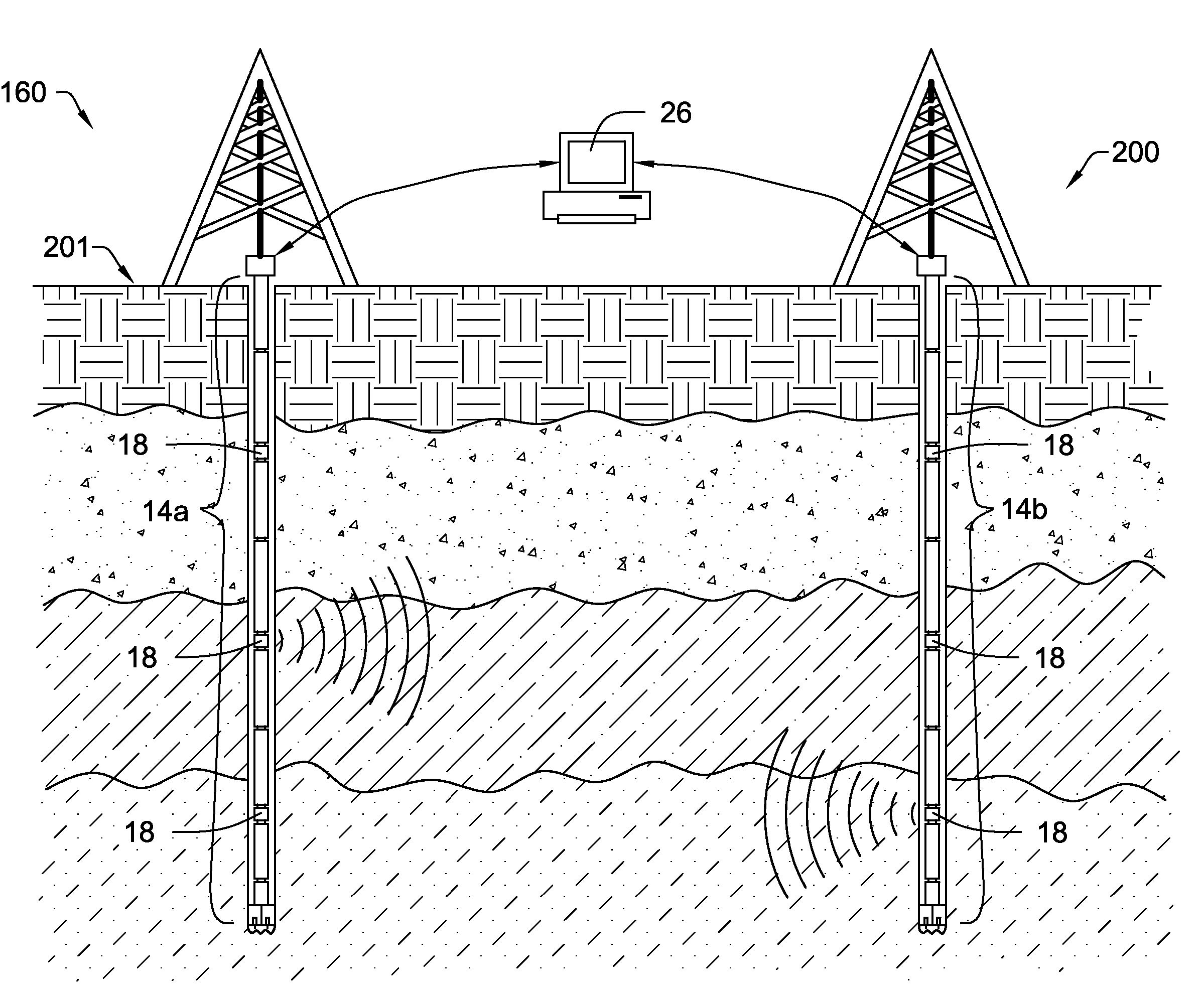
The present invention relates to improved methods and apparatus for gathering data about subsurface formations while drilling or after drilling has stopped. The invention allows for the transmission of large amounts of data to the surface at high speeds. The invention includes a high-speed measurement system with two well bores and two networks of nodes integrated into the well bores. The nodes are synchronized with a common clock source, which allows for the sending of signals between the two networks. The invention also includes a method for synchronizing the clocks of the two networks. The technical effects of the invention include improved data gathering efficiency and reduced drill rig down time.

Problems solved by technology

Nevertheless, although seismology generally provides more usable information than other detection techniques, a drilling company may still only have a 10% chance of finding a new oil field using the technique.
Nevertheless, current downhole seismic data gathering techniques are hindered by several shortcomings.
This process can be quite expensive, not only because of the rig time consumed, but because running the seismic logs can be very expensive.

Method used


Image

  • High-speed, downhole, cross well measurement system
  • High-speed, downhole, cross well measurement system
  • High-speed, downhole, cross well measurement system

Examples


Embodiment Construction

[0032]It will be readily understood that the components of the present invention, as generally described and illustrated in the Figures herein, could be arranged and designed in a wide variety of different configurations. Thus, the following more detailed description of embodiments of apparatus and methods of the present invention, as represented in the Figures, is not intended to limit the scope of the invention, as claimed, but is merely representative of various selected embodiments of the invention.

[0033]The illustrated embodiments of the invention will be best understood by reference to the drawings, wherein like parts are designated by like numerals throughout. Those of ordinary skill in the art will, of course, appreciate that various modifications to the apparatus and methods described herein may easily be made without departing from the essential characteristics of the invention, as described in connection with the Figures. Thus, the following description of the Figures is ...


PUM


Abstract

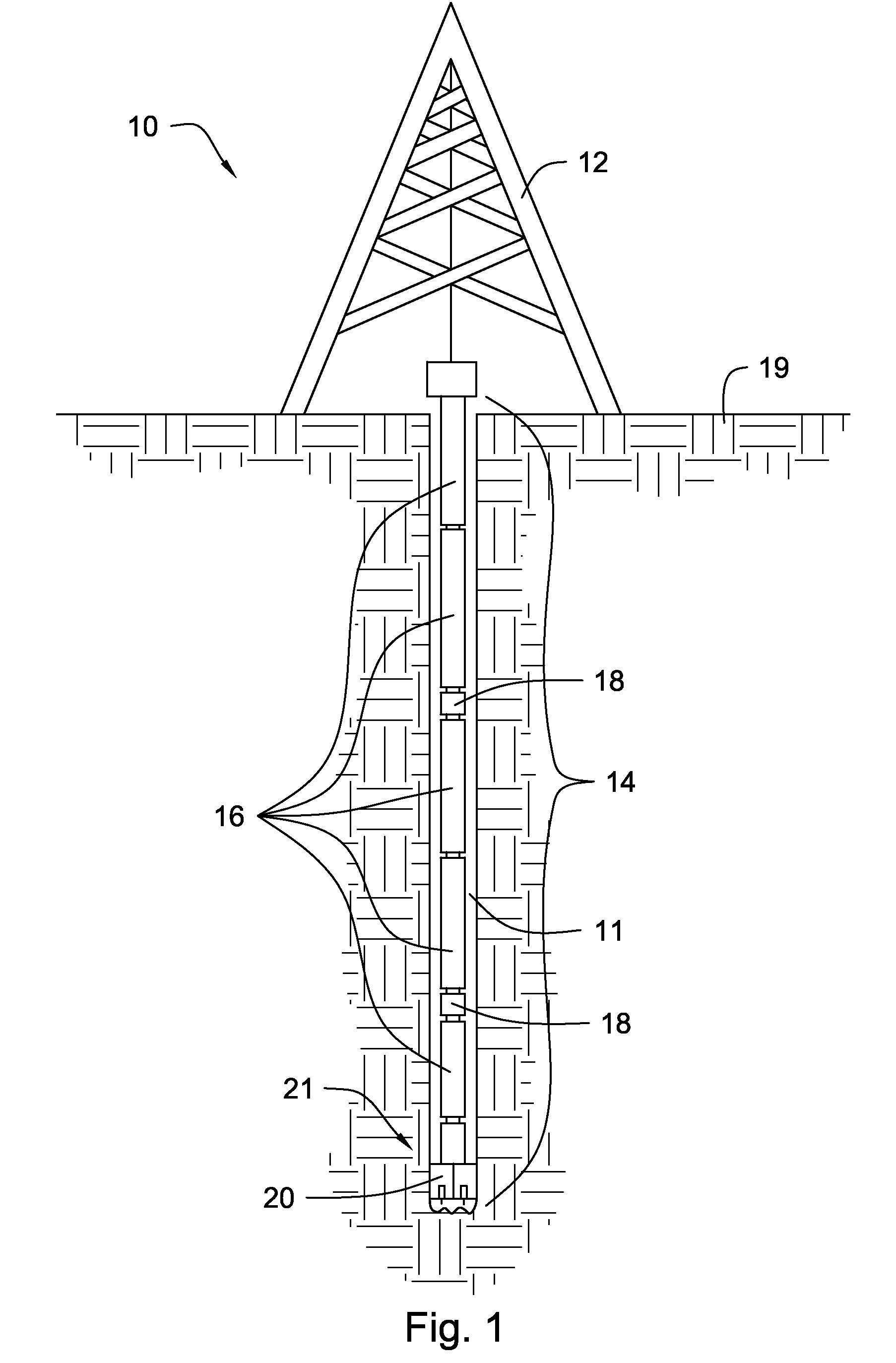
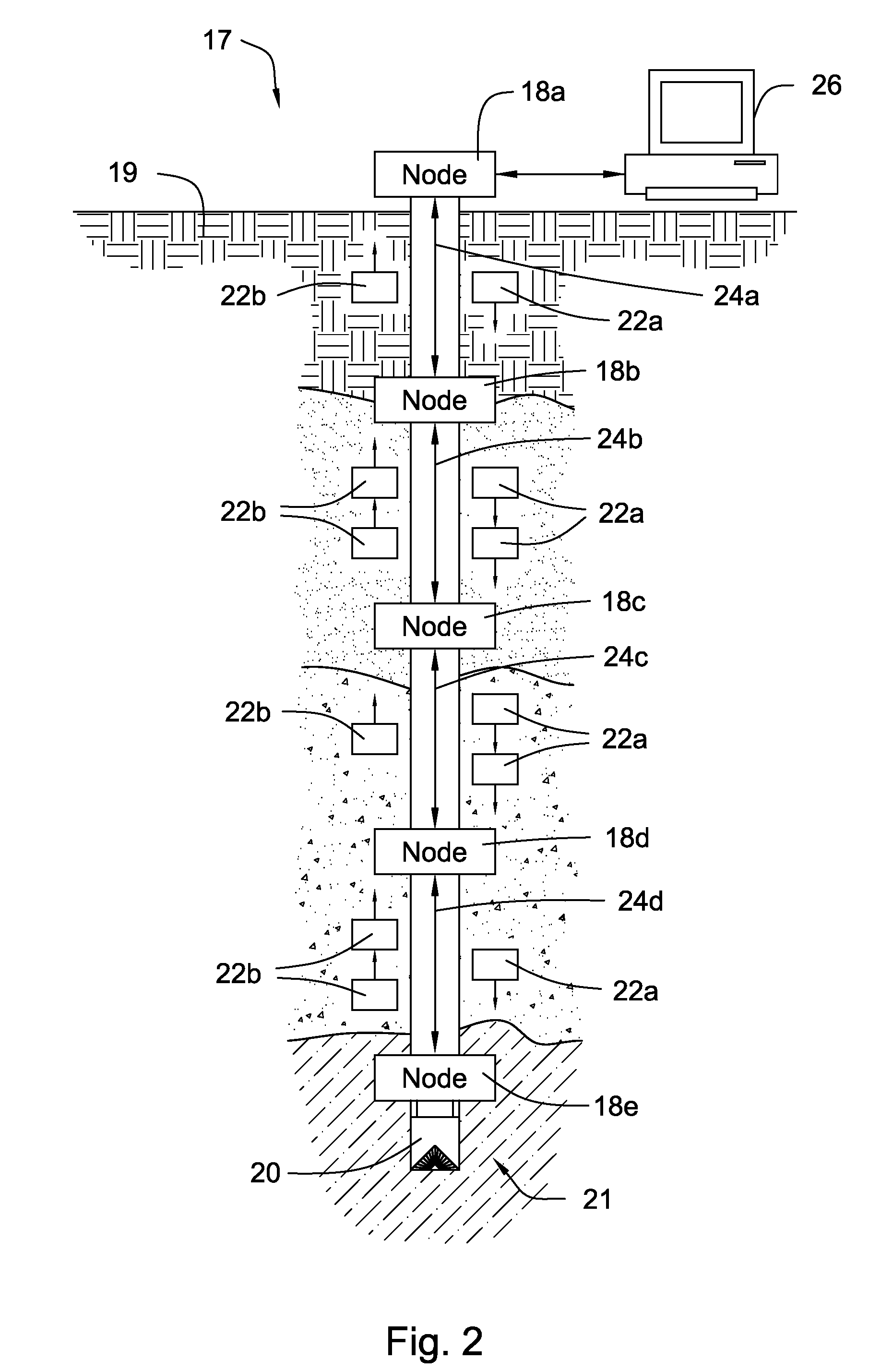
In one aspect of the invention, a high-speed measurement system has a first and a second well bore. A first and second plurality of network nodes is integrated into and spaced at intervals along the first and second well bore, respectively. A communications channel connects each plurality of network nodes forming a first and second downhole network. A signal source is in communication with the first downhole network and a signal receiver is in communication with the second downhole network; and a common clock source is in communication with both the signal source and the signal receiver over the first and second downhole networks, respectively. The signal source and signal receiver are synchronized with the clock source and the signal source is adapted to send a signal to the signal receiver through a subterranean formation.

Description

CROSS-REFERNCE TO RELATED APPLICATIONS[0001]The present application is a continuation-in-part of U.S. patent application Ser. No. 10 / 931,864 filed on Sep. 1, 2004 now abandoned and entitled High-Speed, Downhole, Seismic Measurement System. U.S. patent application Ser. No. 10 / 931,864 is herein incorporated by reference for all that it contains.BACKGROUND OF THE INVENTION[0002]This invention relates to oil and gas drilling, and more particularly to apparatus and methods for gathering seismic data relating to subsurface formations.[0003]In the oil and gas exploration industry, it is useful for geologists to understand underground conditions, such as the type of source rock, reservoir rock, or entrapment areas that may indicate the presence of petroleum and other hydrocarbon reserves. Geologists have historically used several techniques to accomplish this end. For example, geologists may observe surface features, such as rock and soil types, or take core samples. Satellite images, gravi...

Claims


Application Information

Patent Timeline
Patent Type & Authority Patents(United States)
IPC IPC(8): E21B47/12
CPCG01V1/40
Inventor HALLFOX, JOEDURRAND, CHRISTOPHER
Owner SCHLUMBERGER TECH CORP
Learn More