
Method and system for antenna selection diversity with dynamic gain control

a dynamic gain control and antenna selection technology, applied in diversity/multi-antenna systems, polarisation/directional diversity, differential interacting antenna combinations, etc., can solve the problems of receiving signal strength at a given time, adversely affecting system capacity, degrading detector performance, etc., to increase the reliability of communication links and enhance the performance and robustness of receivers

Active Publication Date: 2008-11-18
AVAGO TECH INT SALES PTE LTD
View PDF9 Cites 17 Cited by
  • Summary
  • Abstract
  • Description
  • Claims
  • Application Information

AI Technical Summary

Benefits of technology

Enhances the reliability and robustness of wireless communication links by accurately selecting the strongest signal, reducing errors from noise and transients, and maintaining low transmission overhead.

Problems solved by technology

In such cases the received signal strength at a given time is the result of destructive and constructive interference of the multiple paths arriving from different directions.
Destructive interference degrades the performance of the detector and hence adversely affects the system capacity.
With regard to dwell time on all antennas other than the starting antenna, in practical wireless communications systems, time constraints are imposed to keep the transmission overhead low.
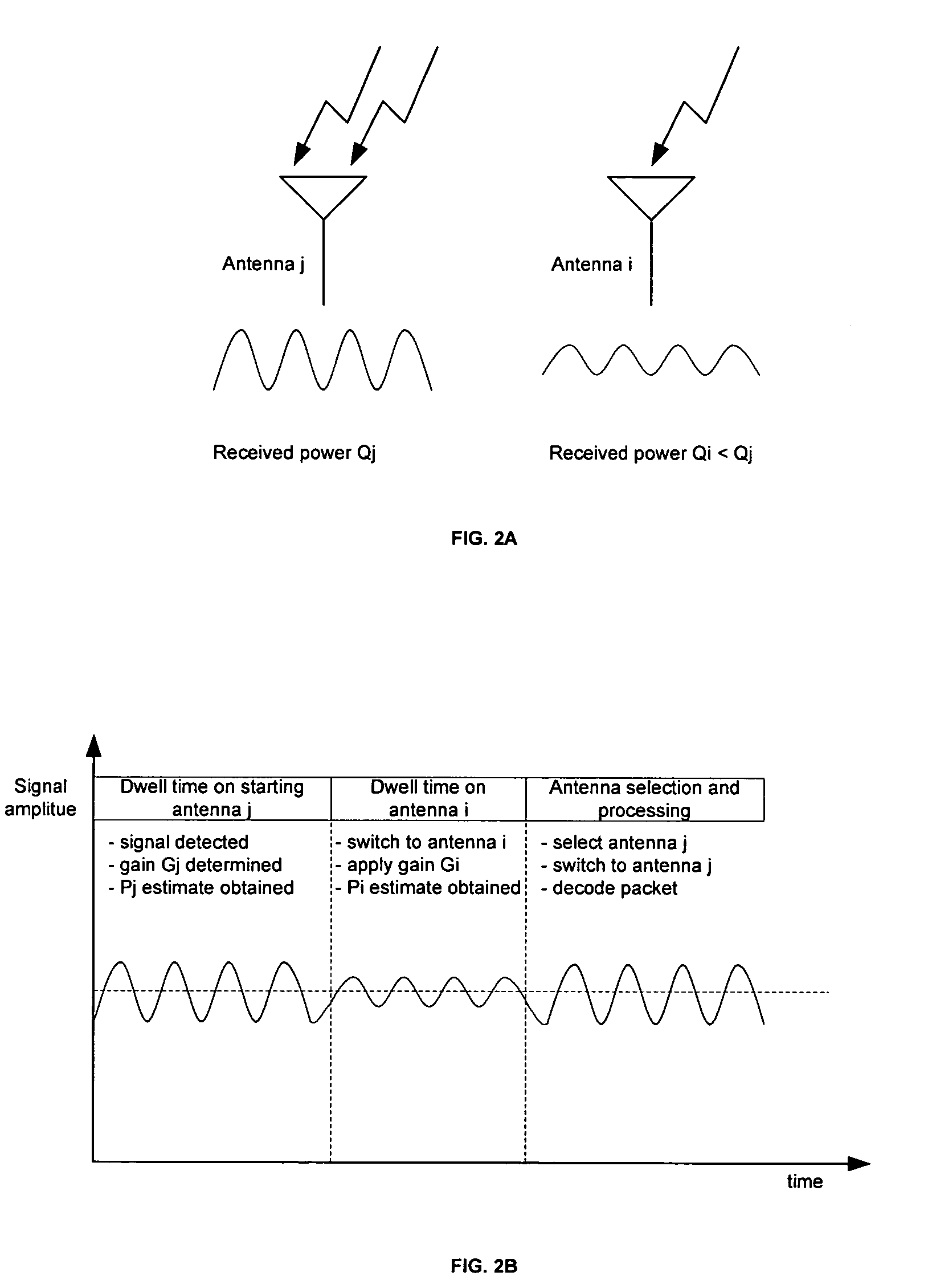
As a result, the dwell time on all antennas other than the starting antenna is insufficient to allow for automatic gain control (AGC) to run its full course during the dwell time on each antenna.
Without automatic gain control, the visibility of the signal strength of all antennas other than the starting antenna is limited and generally leads to inaccurate power estimates Pi.
With regard to the presence of impairments such as noise, transients and offsets, impairments corrupt the power estimates Pi and may result in mis-estimations of the received power.
If the clipped signal in antenna j was in fact the best received signal available to the receiver, the receiver may end up selecting a signal from antenna i, where Pij, because it may not be able to estimate accurately the power of a signal when it is clipped.

Method used


Image

  • Method and system for antenna selection diversity with dynamic gain control
  • Method and system for antenna selection diversity with dynamic gain control
  • Method and system for antenna selection diversity with dynamic gain control

Examples


Embodiment Construction

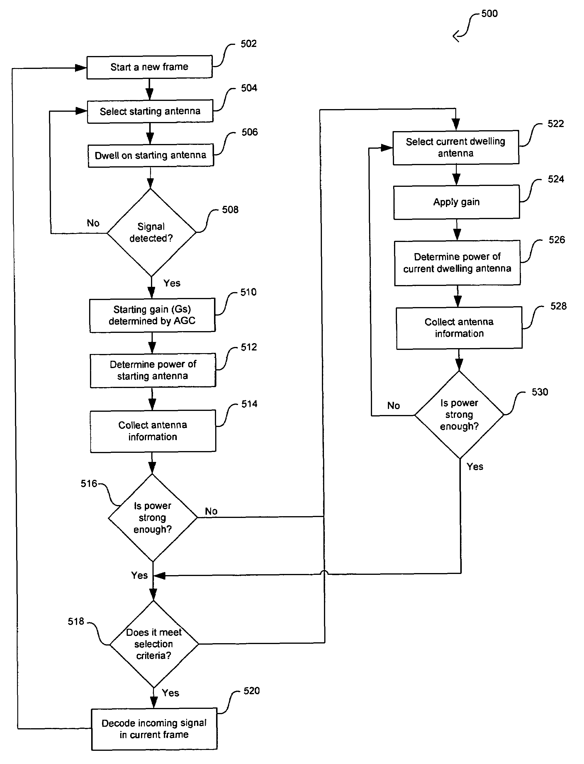
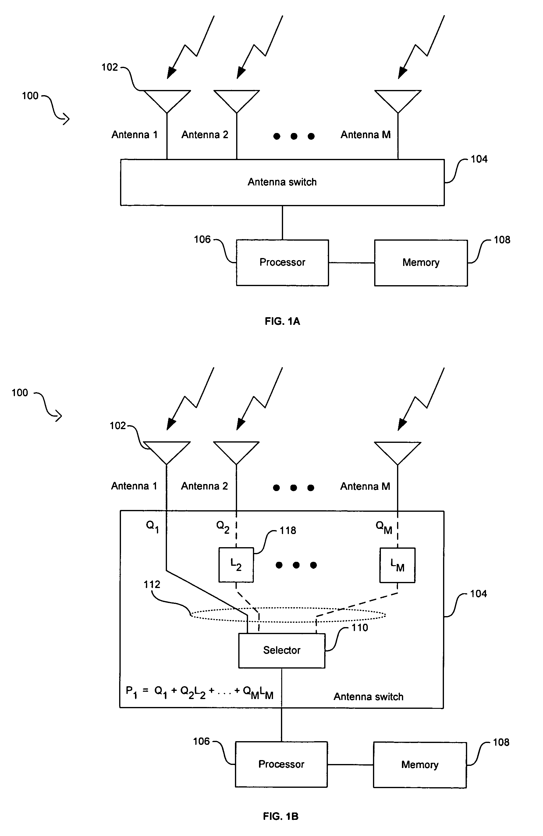
[0030]Certain embodiments of the invention may be found in a method and system for antenna selection diversity with dynamic gain control. Wireless communication systems may utilize receivers with multiple antennas to enhance the performance and robustness of the receiver and to increase the reliability of the communications link. Certain aspects of the method may comprise dwelling on at least one of several antennas in a receiver system in order to select a portion of those antennas for signal processing, determining a gain, and determining a signal quality metric for the dwelled-on antennas. The power may be an estimated received power or it may be a received power. Selecting the portion of antennas that may be used for signal processing may be based on the gain, the estimated signal quality metric, and / or the received signal quality metric of the dwelled-on antennas.

[0031]A starting antenna may be selected from the antennas in the receiver system based on a predetermined criteria,...


PUM


Abstract

A method and system for antenna selection diversity with dynamic gain control. A receiver selects a starting antenna and dwells on it until an incoming signal is detected. An AGC is applied on the received signal and an estimate of the received power is determined for the starting antenna. The receiver may dwell on other antennas if the signal in the first antenna is not strong enough for signal processing. The gain of an antenna may be set by the gain and power levels of the previously dwelled-on antennas and / or by a power coupling factor that exists between the antennas in an antenna switch. The receiver switches through the remaining antennas as long as necessary to select at least one of the antennas for signal processing. Dynamically adjusting the gain of antennas in a diversity system provides a more accurate and efficient antenna selection scheme.

Description

CROSS-REFERENCE TO RELATED APPLICATIONS / INCORPORATION BY REFERENCE[0001]This application makes reference to, claims priority to, and claims the benefit of U.S. Provisional Application Ser. No. 60 / 547,366 filed Feb. 24, 2004.[0002]This application makes reference to:[0003]U.S. Utility application Ser. No. 10 / 810,433 filed Mar. 26, 2004.[0004]U.S. Utility application Ser. No. 10 / 810,186 filed Mar. 26, 2004.[0005]U.S. Utility application Ser. No. 10 / 810,408 filed Mar. 26, 2004.[0006]The above stated applications are hereby incorporated herein by reference in their entirety.FIELD OF THE INVENTION[0007]Certain embodiments of the invention relate to wireless communication. More specifically, certain embodiments of the invention relate to a method and system for antenna selection diversity with dynamic gain control.BACKGROUND OF THE INVENTION[0008]In a wireless communication system, a data stream will most likely experience multiple reflections (multipath) while propagating between the tra...

Claims


Application Information

Patent Timeline
Patent Type & Authority Patents(United States)
IPC IPC(8): H04B7/00H01Q21/29H04B1/10H04B1/18
CPCH01Q21/29H04B1/1027
Inventor MOORTI, RAJENDRA TUSHARHOO, MIN CHUIN
Owner AVAGO TECH INT SALES PTE LTD
Learn More