
System and method for calculating partial differential equations in a hardware graphics pipeline

a technology of partial differential equations and pipelines, applied in the field of computer graphics, can solve the problems of computational intensive process of limited true realistic display of three-dimensional objects, and large computation requirements for realistically rendering and displaying a three-dimensional obj

Inactive Publication Date: 2008-11-18
NVIDIA CORP
View PDF19 Cites 4 Cited by
  • Summary
  • Abstract
  • Description
  • Claims
  • Application Information

AI Technical Summary

Benefits of technology

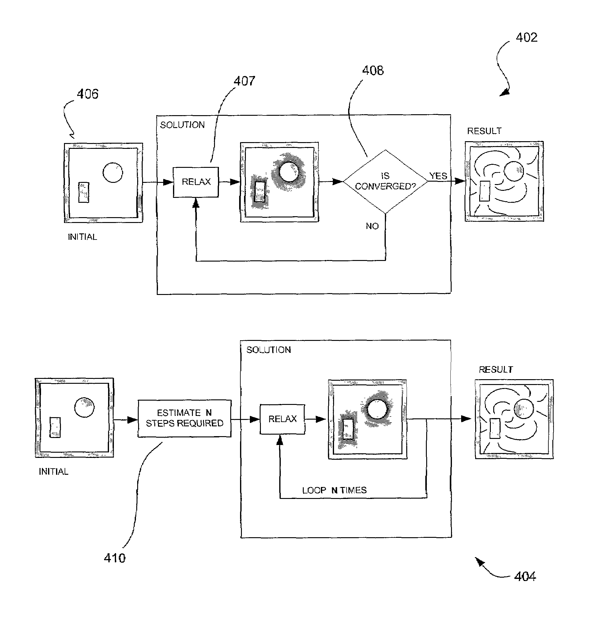
[0013]As an option, it may be determined whether the solution has converged by calculating errors. Such errors may then be summed or evaluated by various techniques after which it may be concluded that the solution has converged if, for example, the sum of errors or the greatest error is less than a predetermined amount. If it is determined that the solution has converged, the processing may be repeated using an incremented parameter value of the equation, for example a time value.

Problems solved by technology

The amount of computations needed to realistically render and display a three-dimensional graphical object, however, remains quite large and true realistic display of three-dimensional objects have largely been limited to high end systems.
Thus the process of rendering and displaying a three-dimensional object can be computationally intensive and may involve a large number of vertices.
Such partial differential equations are traditionally calculated utilizing software and a central processor unit (CPU), since such calculations are generally not cost effective to be implemented in hardware.
However, calculating partial differential equations in software places a heavy burden of computation on the system which may be a significant bottleneck in the application program, and can therefore impede the process of rendering.
Consolidation is often limited, however, by a cost of implementing and manufacturing multiple processing modules on a single chip.
One reason for this increase in cost is that the required integrated circuit would be of a size that is too expensive to be feasible.

Method used


Image

  • System and method for calculating partial differential equations in a hardware graphics pipeline
  • System and method for calculating partial differential equations in a hardware graphics pipeline
  • System and method for calculating partial differential equations in a hardware graphics pipeline

Examples


Embodiment Construction

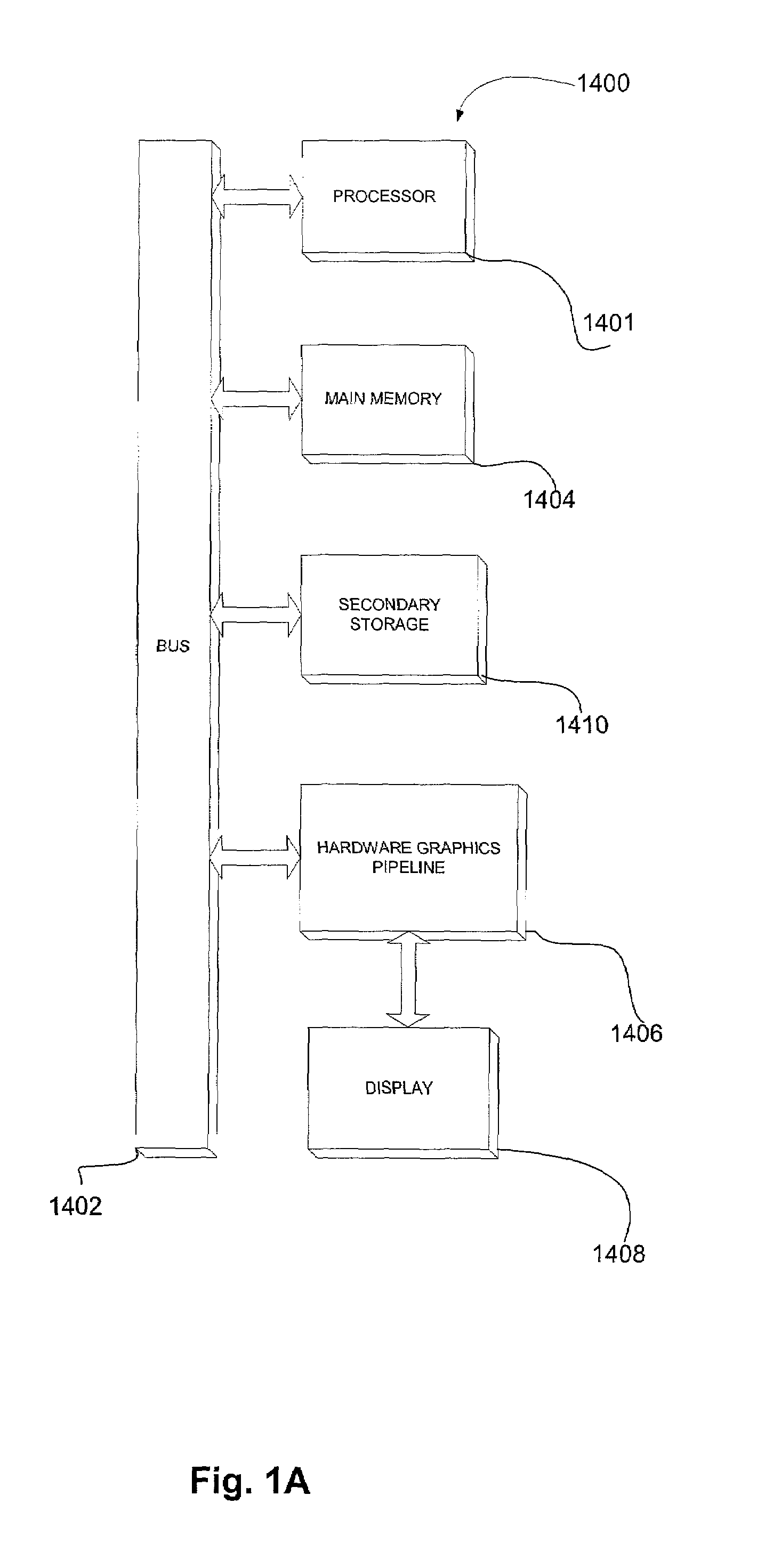
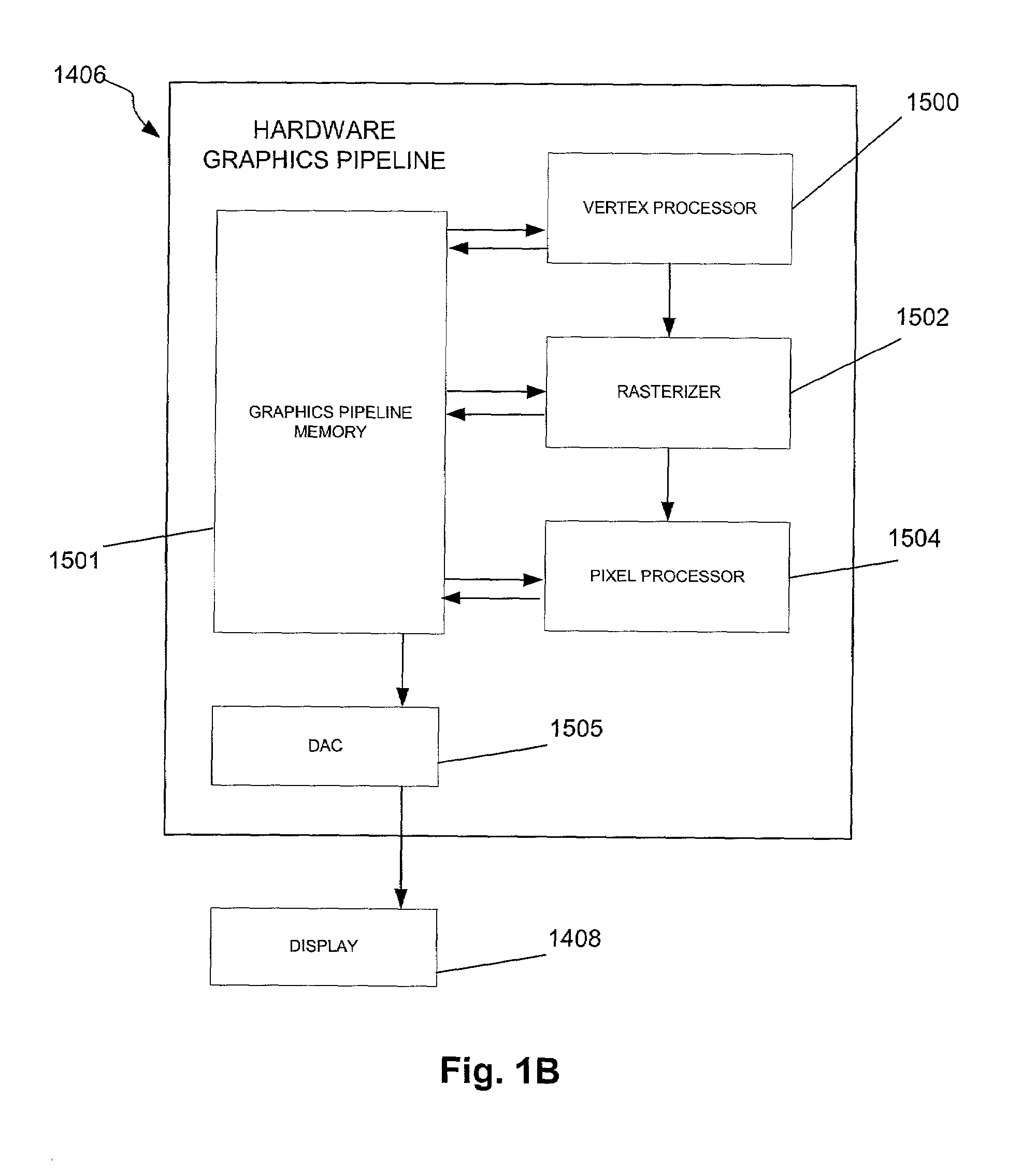
[0031]FIG. 1A is a block diagram of a digital processing system embodying the method and apparatus in accordance with one embodiment. With reference to FIG. 1A, a computer graphics system is provided that may be implemented using a computer 1400. The computer 1400 includes one or more processors, such as processor 1401, which is connected to a communication bus 1402. The computer 1400 also includes a main memory 1404. Control logic (software) and data are stored in the main memory 1404 which may take the form of random access memory (RAM). The computer also includes a hardware graphics pipeline 1406 and a display 1408, i.e. a computer monitor.

[0032]The computer 1400 may also include a secondary storage 1410. The secondary storage 1410 includes, for example, a hard disk drive and / or a removable storage drive, representing a floppy disk drive, a magnetic tape drive, a compact disk drive, etc. Computer programs, or computer control logic algorithms, are stored in the main memory 1404 a...


PUM


Abstract

A system and method are provided for computing partial differential equations in a hardware graphics pipeline. Initially, input is received in a hardware graphics pipeline. Next, the input is processed to generate a solution to a partial differential equation utilizing the hardware graphics pipeline.

Description

FIELD OF THE INVENTION[0001]The present invention relates to computer graphics, and more particularly, to calculating partial differential equations in a computer graphics processing pipeline.BACKGROUND OF THE INVENTION[0002]Three dimensional graphics are central to many applications. For example, computer aided design (CAD) has spurred growth in many industries where computer terminals, cursors, CRT's and graphics terminals are replacing pencil and paper, and computer disks and tapes are replacing drawing vaults. Most, if not all, of these industries have a great need to manipulate and display three-dimensional objects. This has lead to widespread interest and research into methods of modeling, rendering, and displaying three-dimensional objects on a computer screen or other display device. The amount of computations needed to realistically render and display a three-dimensional graphical object, however, remains quite large and true realistic display of three-dimensional objects h...

Claims


Application Information

Patent Timeline
Patent Type & Authority Patents(United States)
IPC IPC(8): G06F17/10
CPCG06F17/13
Inventor JAMES, GREGORY E.
Owner NVIDIA CORP
Learn More