Imaging apparatus and image processing method

a technology of image processing and imaging apparatus, applied in the direction of material analysis using wave/particle radiation, optical radiation measurement, instruments, etc., can solve the problem of deterioration of the s/n ratio, and achieve the effect of dramatically reducing the exposure dosag

Inactive Publication Date: 2014-08-28
CANON KK
View PDF6 Cites 8 Cited by
  • Summary
  • Abstract
  • Description
  • Claims
  • Application Information

AI Technical Summary

Benefits of technology

[0008]Phase imaging using a shearing interferometer can be applied to image diagnosis and various non-destructive inspections. X-ray phase imaging in particular attracts attention as a new image diagnostic method, because...

Problems solved by technology

In this kind of phase imaging, a fundamental problem is how to improve the image quality with decreasing noises and artifacts.
Even if the apparatus uses a visible l...

Method used


Image

  • Imaging apparatus and image processing method
  • Imaging apparatus and image processing method
  • Imaging apparatus and image processing method

Examples


Embodiment Construction

[0029]Preferred embodiments of the present invention will now be described with reference to the accompanying drawings. In each drawing, same composing elements are denoted with a same reference numeral, where redundant description is omitted.

[0030]In the present embodiment, an example of using an x-ray Talbot interferometer as means of acquiring a differential phase image will be described. A method for acquiring a differential phase image, to which the present invention can be applied, is not limited to this method, but any shearing interferometer can be used only if a differential phase image of a subject (test object) can be acquired. Light used for measurement is not limited to an x-ray, but may be an electromagnetic wave having any wavelength. An x-ray in this description refers to light of which energy is at least 2 keV and at most 200 keV.

[0031](Configuration of Imaging Apparatus)

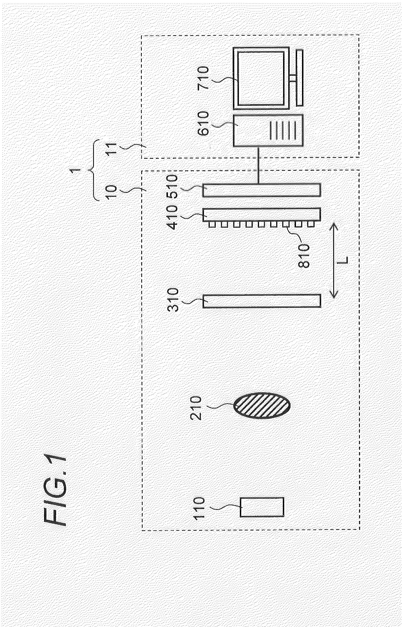
[0032]FIG. 1 is a diagram depicting a configuration of an imaging apparatus according to this em...


PUM


Abstract

Disclosed is an imaging apparatus for generating data of a phase image based on an interference pattern acquired by a shearing interferometer, including: a differential phase data calculating unit that calculates first differential phase data expressing a change of a phase in a first direction and second differential phase data expressing a change of a phase in a second direction, based on interference pattern data generated by an electromagnetic wave transmitted through a subject; a second-order differential phase data calculating unit that calculates first second-order differential phase data by differentiating the first differential phase data in the first direction, and calculates second second-order differential phase data by differentiating the second differential phase data in the second direction; and a phase data calculating unit that calculates the phase image by solving a second-order differential equation including the first and second second-order differential phase data as functions.

Description

TECHNICAL FIELD[0001]The present invention relates to a technique to generate data for a phase image and a differential phase image from an interference pattern acquired by a shearing interferometer.BACKGROUND ART[0002]A searing interferometer is means of visualizing a phase change of light, caused by a subject, using a shift of fringes. The fringes are generated by separating coherent light, such as beams irradiated from a single light source, generating distortion of wavefronts in one beam by the subject, and slightly shifting the other beam. This searing interferometer is used, for example, for improving the visibility of a subject in the field of phase contrast microscopes.[0003]As a shearing interferometer, an interferometer using Talbot interferometry is known. According to the Talbot interferometry, light from a light source is irradiated onto a subject, and light, of which phase is changed by transmitting through the subject, is guided to a diffraction grating. The light dif...

Claims


Application Information

Patent Timeline
IPC IPC(8): G01J9/02G06K9/62
CPCG01J9/0215G06K9/62A61B6/00G01N23/04A61B6/484A61B6/5258G01N2223/345G01N2223/401G01N23/041G06F18/00
Inventor NAGAI, KENTAROTAKEDA, MITSUO
Owner CANON KK
Why Eureka
Try Eureka