Tube cleaning tool

a cleaning tool and tube technology, applied in the field of cleaning tools, can solve the problems of inability to control the pressure exerted by the cutter blades on the inside wall of the tube, the construction of this tool is relatively complex, and the material used is relatively expensiv

Inactive Publication Date: 2008-11-25
LYLE DANIEL C
View PDF25 Cites 22 Cited by
  • Summary
  • Abstract
  • Description
  • Claims
  • Application Information

AI Technical Summary

Benefits of technology

[0005]The present invention relates to the mechanical scraping and cleaning of soft and hard deposits, such as sludge and manganese, from the inner surface of a tube, such as those found in condensers and heat exchangers. The present invention provides a device for the scraping and cleaning of the inside wall of the tube. This tube cleaning device, or projectile, is propelled forward by a high-pressure fluid spray injected into a tube. This high-pressured fluid injection is sufficient to advance the device through the tube, allowing the device to scrape or otherwise dislodge incrustations or other accumulations from the interior wall of the tube.

Problems solved by technology

There are some difficulties with this arrangement, a few of which are the limited contact that a cutter blade has with the inner wall of the tube and the lack of ability to control the pressure exerted by the cutter blades on the inside wall of the tube.
However, the construction of this tool is relatively complex, and is fabricated from relatively expensive materials.
These plastic tools are not as effective as the type of tool shown in 488, but they are adequate for certain applications where maximum cleaning is not necessary or desired.

Method used


Image

  • Tube cleaning tool
  • Tube cleaning tool
  • Tube cleaning tool

Examples


Embodiment Construction

[0021]While preferred embodiments of the present invention have been illustrated and described herein, it is to be understood that various changes may be made therein without departing from the spirit of the invention, as defined by the scope of the appended claims.

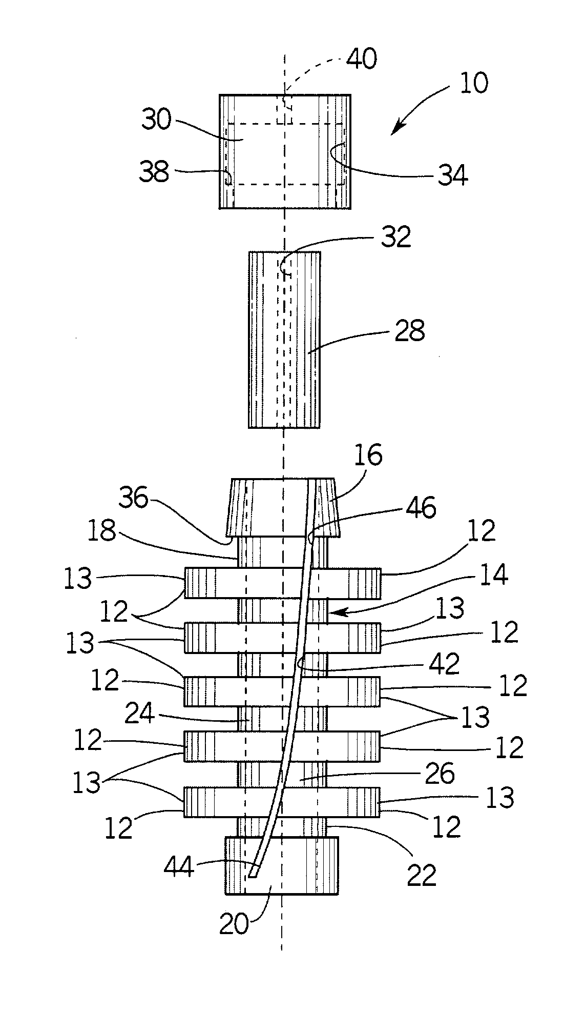
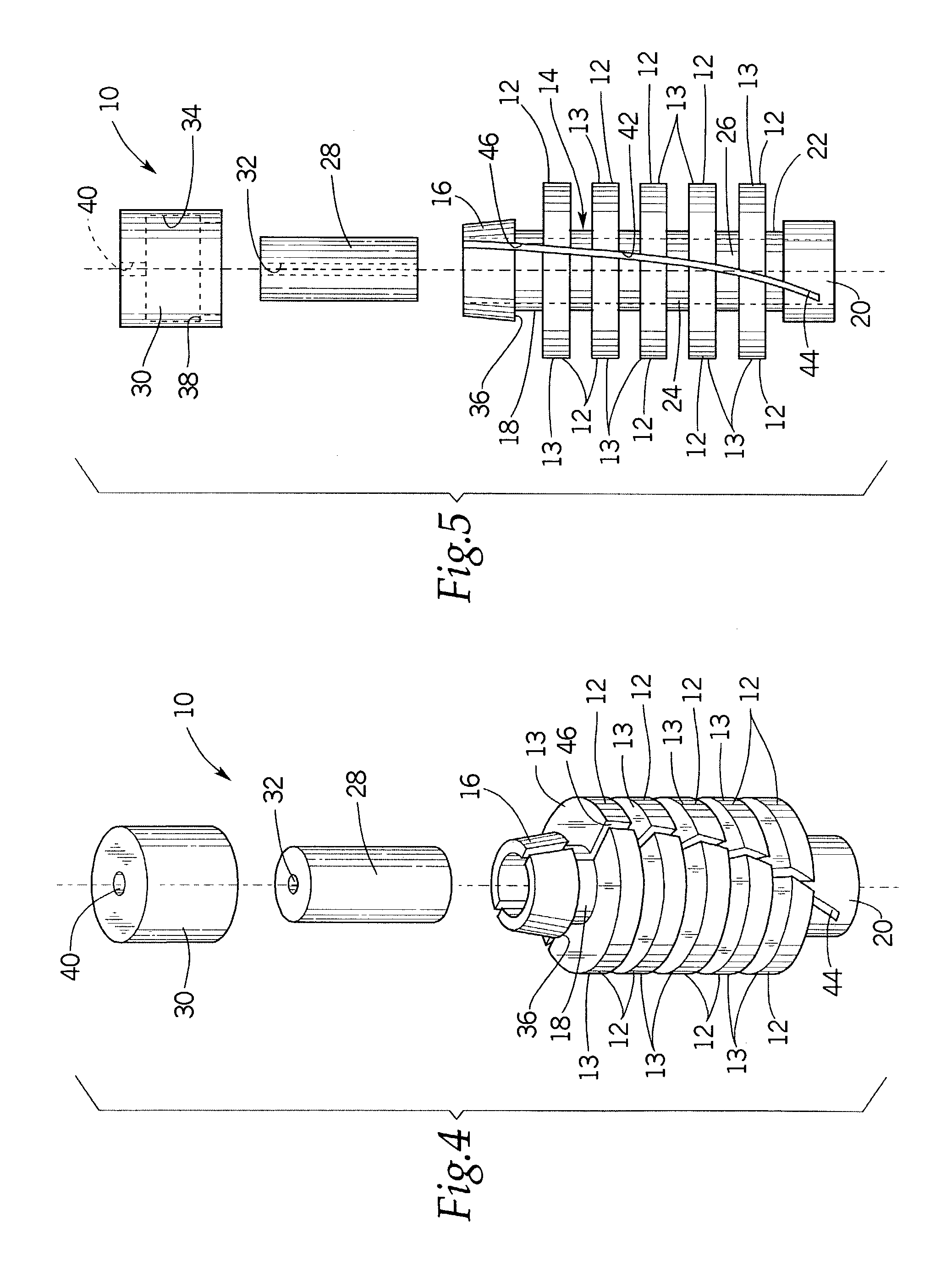
[0022]FIGS. 4 through 8 show a tube cleaner or projectile 10 that is a preferred embodiment provided by the present invention. Preferably, cleaner 10 is one piece of molded somewhat flexible plastic, preferably a suitable wear-resistant polymer. Cleaner 10 includes a series of cutters or scrapers 12 that are formed on the outer surface of a hollow, split cutter support 14. Each cutter 12 defines two or more cutter sections 13 that form a generally circular cutting surface that conforms to the inner surface of the tube through which cleaner 10 is propelled to clean the inner surface of the tube. A split tail portion 16 is formed on end 18 of support 14. Although tail portion 16 may be split to form two or more sections, tw...


PUM


Abstract

A cleaning device, or projectile, cleans the inside surface of a tube as it is propelled by a liquid through the tube by mechanically scraping and cleaning soft and hard deposits, such as sludge and manganese, from the inner surface of the tube, such as those found in condensers and heat exchangers. The tube cleaning device, or projectile, is propelled forward by a high-pressure fluid spray injected into a tube. This high-pressured fluid injection is sufficient to advance the device through the tube, allowing the device to scrape or otherwise dislodge incrustations or other accumulations from the interior wall of the tube. The tool cleans the inside surface of a tube as the tool travels through the tube and includes a compressible bushing and a series of cutters secured to a split support that defines a cavity for receiving the bushing, the support being adapted to be opened and closed to receive and contain the bushing. Each cutter defines a cutting surface of a diameter that depends on the diameter and hardness of the bushing. Use of bushings with various diameters and hardness provides effective cutting surfaces of various diameters and scraping forces of various magnitudes. Each cutter can define a mounting groove to receive a metal cutter for tougher deposits.

Description

BACKGROUND OF THE INVENTION[0001]The present invention relates to a cleaning tool for the loosening and removal of deposits from the interior wall of tubes.[0002]It is well known that fluid driven projectiles or scrapers can be used for the removal of mud, slim, scale or other deposits from the interior wall of a tube, such as a condenser, heat exchanger or similar tubing. Such scrapers generally comprise one or more cutters or scrapers that extend outwardly from a support. One type of device has a cutter that contains two blades that contact the inside of the tube. Generally, the tail portion of the projectile will contain a section which will enable the projectile to be forced through the tubing by the use of fluid and will also allow for some fluid to pass through the projectile device, cleaning debris from in front of the projectile as the projectile moves through the tube. There are some difficulties with this arrangement, a few of which are the limited contact that a cutter bl...

Claims


Application Information

Patent Timeline
Patent Type & Authority Patents(United States)
IPC IPC(8): B08B1/00
CPCB08B9/0557F16L55/38F28G1/12F16L2101/12
Inventor LYLE, DANIEL C.
Owner LYLE DANIEL C
Why Eureka
Try Eureka