Raised flooring system and method

a raised floor and floor technology, applied in the direction of building scaffolds, walls, building roofs, etc., can solve the problems of increasing power requirements, increasing the burden on heating/cooling, electrical power distribution and cabling systems, and often landlords are forced to solve, so as to improve structural integrity, facilitate assembly, and enhance structural design

Inactive Publication Date: 2008-11-25
OWEN DAVID D
View PDF19 Cites 32 Cited by
  • Summary
  • Abstract
  • Description
  • Claims
  • Application Information

AI Technical Summary

Benefits of technology

[0022]In an exemplary embodiment, the projections include a recess for aiding an enhanced setup process. The recess contains a wedge profile that aids in guiding the pedestal projections into corresponding receiving slots found within the base floor pads. The recess configuration in conjunction with the twist-and-lock system also assists in relaxing the individual and cumulative tolerance requirements between base floor pads. Because the receiving slot provides a larger opening than the corresponding size of the projection, less readjustment or disassembly is required because of improper base floor pad orientation, configuration, and the like. The projection recess further relaxes the overall tolerances as well aids in positioning the projection within the penetrating or receiving slot of the base floor pad.
[0023]Additional advantages of the disclosed locking system allows an assembler to quickly place the base floor pads throughout any room requiring a raised floor assembly. The lightweight design and enhanced tolerance allotment allows the pads to be easily and expeditiously maneuvered into position. The pedestals are then placed into corresponding slots located within each of the base floor pads. By turning the pedestals, a locking position is acquired, which guarantees that the pedestal caps are in the proper location for receiving the much heavier and more difficult to maneuver work floor panels. A work floor panel depending on the application can be made from any number of materials, including wood, aluminum, stone, or most commonly, a steel pan filled with approximately one-inch of concrete. Therefore, the importance of proper pedestal positioning should be appreciated when it results in the successful positioning of a two-foot by two-foot steel square filled with one-inch thick concrete.
[0024]The locking construction therefore provides reassurance to even an unskilled assembler that the positions between pedestals are properly located for the installation of the work floor panels. In addition, the increased tolerances in the locking assembly construct reduces, if not eliminates the need to reposition the base floor pads, thus saving time and money.
[0025]In yet another embodiment, the projections comprise an angle complementary to the locking aperture surface profile. In one embodiment the angle is 45 degrees reducing the tendency for movement in the flooring system resulting from racking or axial forces. Another feature of the flooring system is extending the projection profile along the length of the locking aperture to further strengthen the system against undesirable forces.
[0027]Another feature of the flooring system is the addition of an adhesive member to the cap portion of the pedestals. The adhesive member then attaches to an underside of the work floor panels. The adhesive members aid in reducing lateral movement of the working floor panels as well enhances the overall system's structural integrity.

Problems solved by technology

Now, due to the changes in market economies, frequently landlords are forced to solve problems of substantial increases in power requirements, additional cooling and cable distribution.
Modem day office requirements have placed burdens on heating / cooling, electrical power distribution and cabling systems which were never anticipated when even the most modern office buildings were built.
Physical concentrations of PCs and other electrical enhancements such as facsimile machines, copiers, printers, scanners, and in particular, the personnel operating the equipment, have placed extra-ordinary burdens on the most sophisticated and powerful heating, ventilating and air conditioning systems.
These concentrations of equipment and personnel generated heat are most frequently offset by increasing the velocity of chilled air from overhead diffusers, usually at the expense of other areas, and to the discomfort of personnel.
Convenient, horizontal retro-feeding of electrical power wiring or cabling through finished stud and dry wall partitions is particularly difficult, costly, disruptive and sometimes, impossible unless sufficient conduit has been pre-installed.
This plenum approach has severe difficulties and limitations.
Once additional power is in place, an undesirable result is a comparable increase in generated heat, requiring more cooling.
Typically such additional heat loads have not been anticipated nor dealt with in the base building design or construction.
Increases in air velocities result in increased noise levels and are really nothing more than cycling air more rapidly through the base system which has a finite heat absorbing capacity.
In the event of such a fire, the egress of the supplemental conditioning air from the plenum would obviously be undesirable.
Prior proposals for supplemental flooring systems have all been excessively complex such that they required skilled installers for disproportionately long periods of time.
Further, prior proposed systems have not been fully modular and had inadequate provision for access to service lines extending through such a system.

Method used


Image

  • Raised flooring system and method
  • Raised flooring system and method
  • Raised flooring system and method

Examples


Embodiment Construction

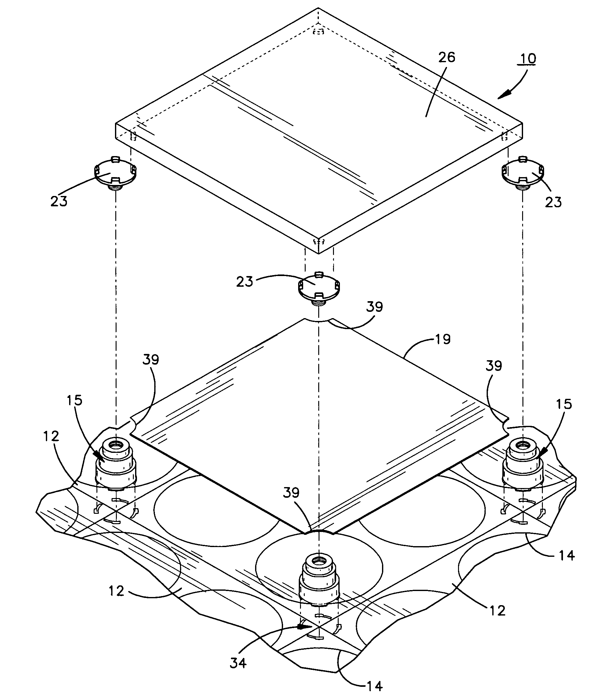
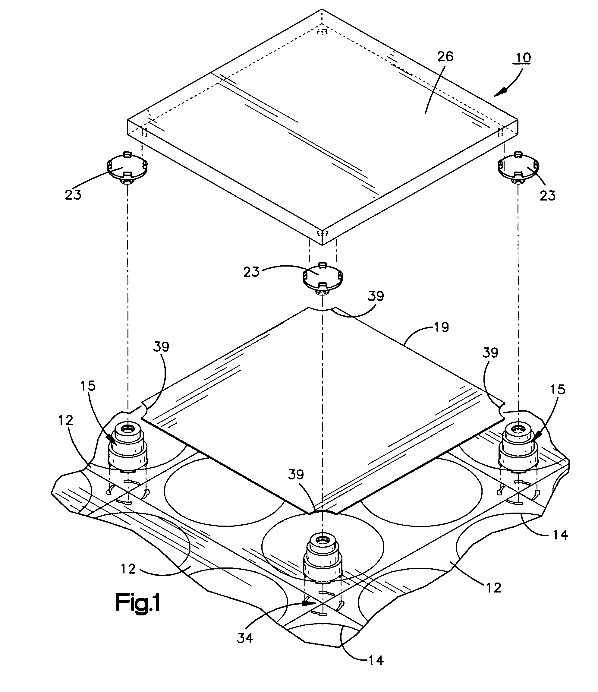
[0041]Referring to the drawings and to FIG. 1 in particular, a fragmentary portion of an assembled flooring system utilizing plastic or metal components is shown generally at 10. A plurality of base floor pads 12 make a first level of the assembly 10. Each base floor pad has four relatively large through apertures 14 which are provided to minimize weight and material consumed and to provide for the flexible positioning of stabilizing pedestals 13 discussed later in detail.

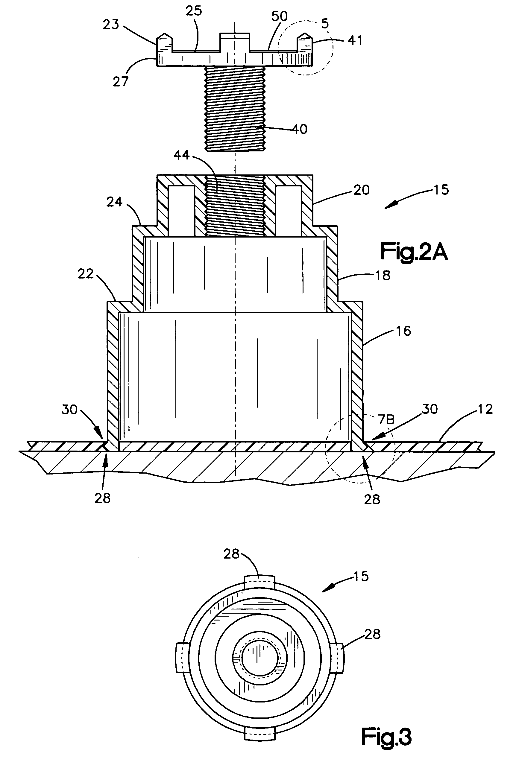
[0042]Also shown in FIG. 1 is a plurality of pedestals 15. The pedestals include base, central and top conical segments 16, 18, and 20, as depicted in FIGS. 2A and 2B. The conical segments are axially aligned and contiguous to define support surfaces for separation plates. More specifically, a first annular surface 22, which is flat and horizontal when in use, interconnects a base and central segments for supporting a lower separator plate 17 at a second level shown in FIG. 4B. Similarly, at a third level, an upper...


PUM


Abstract

A raised flooring system having a sub-work surface is disclosed. The system includes a plurality of pedestal assemblies, a plurality of base floor pads for placing and securing the pedestal assemblies, and a locking assembly for securing the pedestal assemblies to the base floor pads. The locking assemblies include a plurality of projections extending from the pedestal assemblies, a receiving aperture located in each of the base floor pads for receiving the projections in a first position, and a locking aperture in communication with the receiving aperture for locking the pedestal when in a second position to relative to the base floor pad. Inserting the projections into the receiving apertures and rotating the pedestals from the first position to a second position secure the pedestals to the base floor pads, one to another, thus providing exact registration of the pedestals for the ultimate installation of the work floor panels.

Description

FIELD OF THE INVENTION[0001]This invention relates to an accessible raised floor system for use in office buildings or the like, and more specifically, a locking floor system designed for quick assembly.BACKGROUND OF THE INVENTION[0002]Historically, building owners have not had to deal with tenant requirements for supplemental cooling, power and cabling, with the exception of special purpose computer or trading rooms. These special purpose rooms have been dealt with almost as if they were separate structures. Unless a building was occupant owned, a tenant had to deal with these requirements. Now, due to the changes in market economies, frequently landlords are forced to solve problems of substantial increases in power requirements, additional cooling and cable distribution.[0003]As the use of office space has evolved since the development of personal computers (PC), there has been an escalation in the need for and frequency of re-organization and re-configuration of office space. En...

Claims


Application Information

Patent Timeline
Patent Type & Authority Patents(United States)
IPC IPC(8): E04B1/00E04B2/82E04B9/00E04C2/52E04G1/22
CPCE04F15/024E04F15/02452E04F15/0247
Inventor OWEN, DAVID D.
Owner OWEN DAVID D
Why Eureka
Try Eureka