TDM switching system and ASIC device

a switching system and asic technology, applied in data switching networks, time-division multiplexing selection, multiplex communication, etc., can solve the problems of increasing the footprint, manufacturing cost, power consumption, and the inability of prior switching mechanisms and techniques to meet these needs, and the previous techniques involving relatively large number of such components become less desirable, etc., to achieve the effect of reducing the footprint, power consumption, and reducing the cost of manufacturing

Inactive Publication Date: 2008-11-25
CISCO TECH INC
View PDF13 Cites 5 Cited by
  • Summary
  • Abstract
  • Description
  • Claims
  • Application Information

AI Technical Summary

Benefits of technology

[0008]Particular embodiments of the present invention may provide one or more technical advantages. For example, in certain embodiments, a switching system includes multiple ASIC devices on each network interface card, at least one of which allows data to be switched from an associated incoming network interface to an outgoing network interface associated with the same card. Remaining ASIC devices allow data to be switched from an associated incoming network interface to outgoing network interfaces associated with one or more other cards in the system. Using this approach, certain embodiments may allow for increased scalability and port density while reducing manufacturing cost and may take full advantage of ASIC devices designed and fabricated specifically for TDM switching.
[0009]In certain embodiments, an ASIC device provides TDM switching capabilities without the many hardware components and associated circuitry typically required for previous TDM switching architectures. In certain emb

Problems solved by technology

However, prior switching mechanisms and techniques are often inadequate to satisfy these needs, at least partially because of the many hardware components and associated circuitry typically required for their implementation.
Since each additional component associated with a switching mechanism in general adds to its footprint, manufacturing cost, and power consumption, previous techniques involving relatively large number of such components become less desirable as switching systems become sm

Method used


Image

  • TDM switching system and ASIC device
  • TDM switching system and ASIC device
  • TDM switching system and ASIC device

Examples


Embodiment Construction

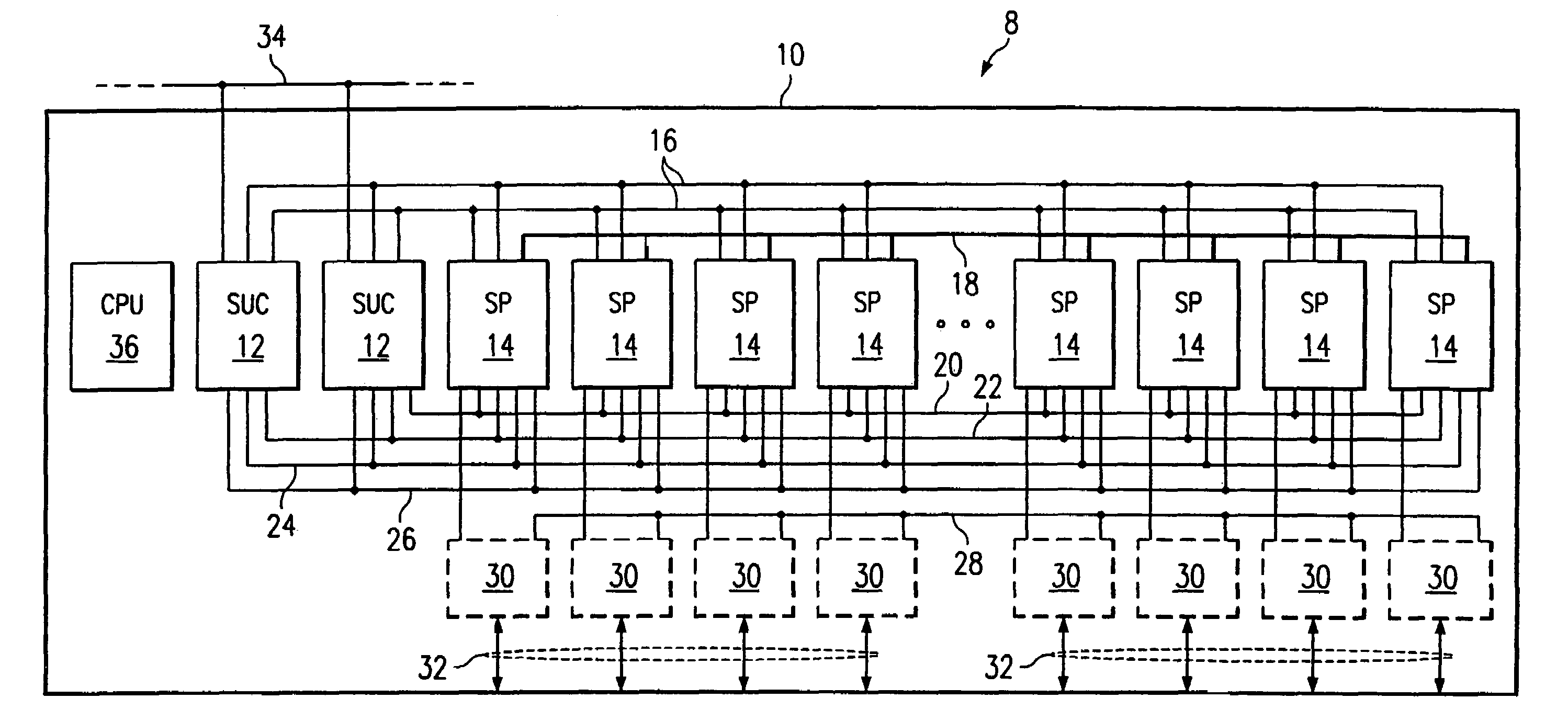
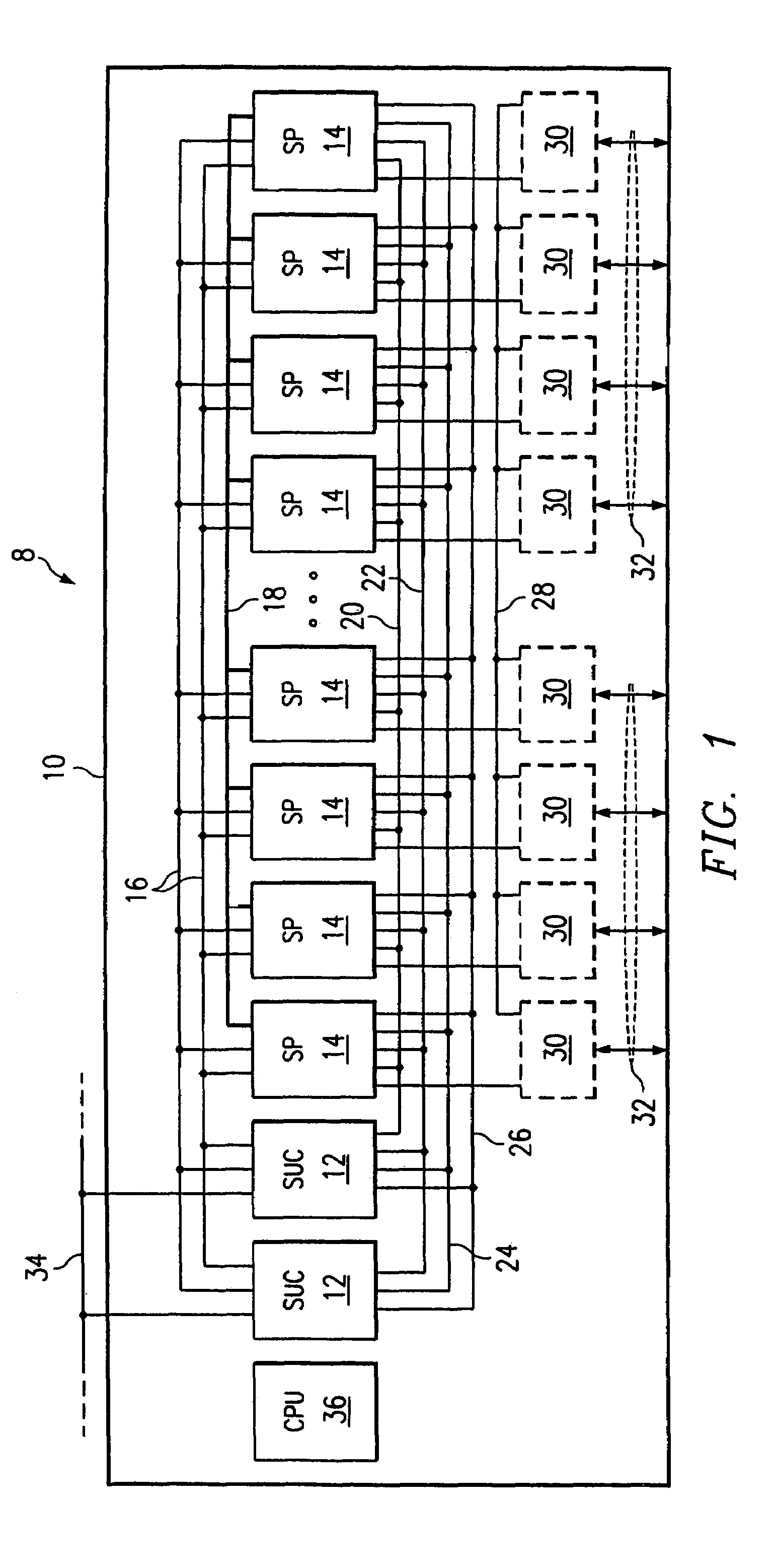
[0024]FIG. 1 illustrates an example system 8 including one or more switching units 10. In one embodiment, each switching unit 10 is a programmable switching unit that switches time division multiplexed (TDM), packet-based, or other suitable digital signals associated with voice, data, or other appropriate traffic between incoming and outgoing ports, lines, trunks, or other suitable telecommunications network interfaces. In general, switching unit 10 may operate at least in part subject to control of suitable software within one or more associated host computers and may be coupled to such host computers using one or more suitable communications links. Although switching unit 10 is discussed, those skilled in the art appreciate that the present invention may apply similarly to a wide variety of other telecommunications devices and that the present invention encompasses all such applications.

[0025]In one embodiment, switching unit 10 includes two or more redundant switching unit contro...


PUM


Abstract

In one embodiment, a switching system includes a backplane and multiple cards that each support multiple ASIC devices. Each ASIC device is associated with a subset of the network interfaces associated with the switching system. At least one ASIC device on a card may communicate switched data to an outgoing network interface associated with the card. Remaining ASIC devices on the card may communicate switched data to one or more other cards, using the backplane, for communication to one or more outgoing network interfaces associated with the other cards. In another embodiment, a device for switching data from a first bus to a second bus in a TDM switching system is provided. In another embodiment, a method for switching data between a plurality of network interfaces in a switching system is disclosed.

Description

RELATED APPLICATIONS[0001]This application is a continuation of U.S. patent application Ser. No. 10 / 430,828 filed May 6, 2003 and entitled “TDM Switching System and ASIC Device”, now U.S. Pat. No. 6,785,270, which is a continuation of U.S. patent application Ser. No. 09 / 327,700 filed Jun. 8, 1999 and entitled “TDM Switching System and ASIC Device,” now U.S. Pat. No. 6,587,461 B1.TECHNICAL FIELD OF THE INVENTION[0002]This invention relates to the field of telecommunications, and more particularly to a TDM switching system and ASIC complex.BACKGROUND[0003]Many telecommunications devices include backplanes for transmitting digital information between components of the devices. For example, a telecommunications switching system might include a backplane for transmitting digital data representing voice signals between cards associated with incoming and outgoing ports. A switching system would also include a switching mechanism to associate incoming data received at an incoming port with ...

Claims


Application Information

Patent Timeline
IPC IPC(8): H04L12/52H04L12/50H04Q11/04
CPCH04Q11/04H04Q2213/13103H04Q2213/13292H04Q2213/13299H04Q2213/1332H04Q2213/13322
Inventor PARRISH, BRENT K.NIEBEL, WERNER E.
Owner CISCO TECH INC
Why Eureka
Try Eureka