Suppression element for vortex-induced vibrations

a technology of suppression element and vortex, which is applied in the direction of protective foundation, ship vibration reduction, bulkhead/pile, etc., can solve the problems of pipeline vibration, complicated and expensive manufacture of such elements, and achieve the effect of ready-to-manufactur

Inactive Publication Date: 2008-12-02
LANKHORST SPECIAL MOLDINGS
View PDF12 Cites 25 Cited by
  • Summary
  • Abstract
  • Description
  • Claims
  • Application Information

AI Technical Summary

Benefits of technology

[0006]It is an object of the invention to provide an improved suppression element, and more specifically a suppression element which can be readily manufactured. To this end, the invention provides a suppression element for vortex vibrations, comprising an envelope for at least partly envelopi

Problems solved by technology

The vortices on the back side can also cause vibrations in the pipelines.
A drawback of th

Method used


Image

  • Suppression element for vortex-induced vibrations
  • Suppression element for vortex-induced vibrations
  • Suppression element for vortex-induced vibrations

Examples


Embodiment Construction

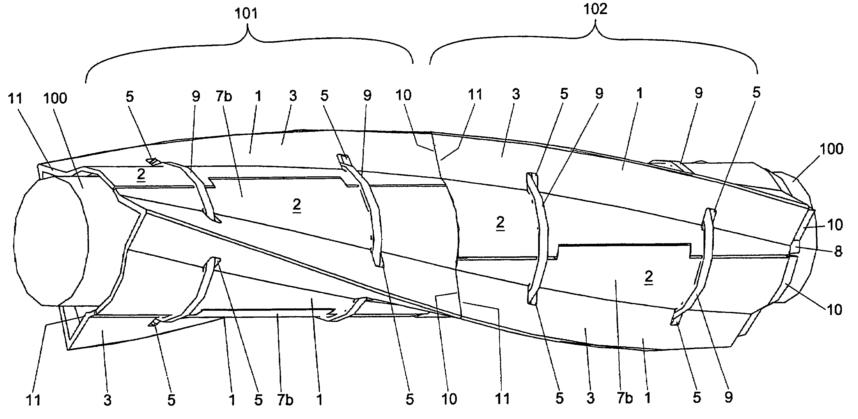
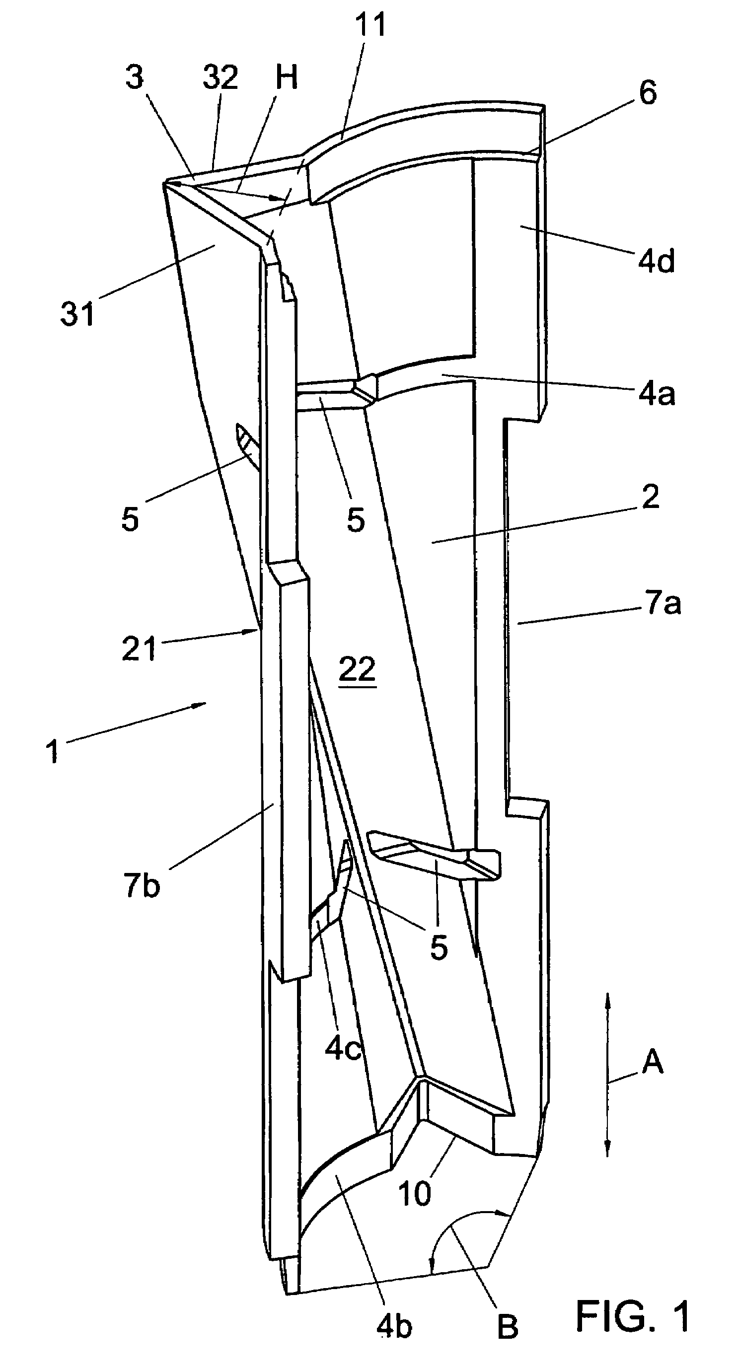
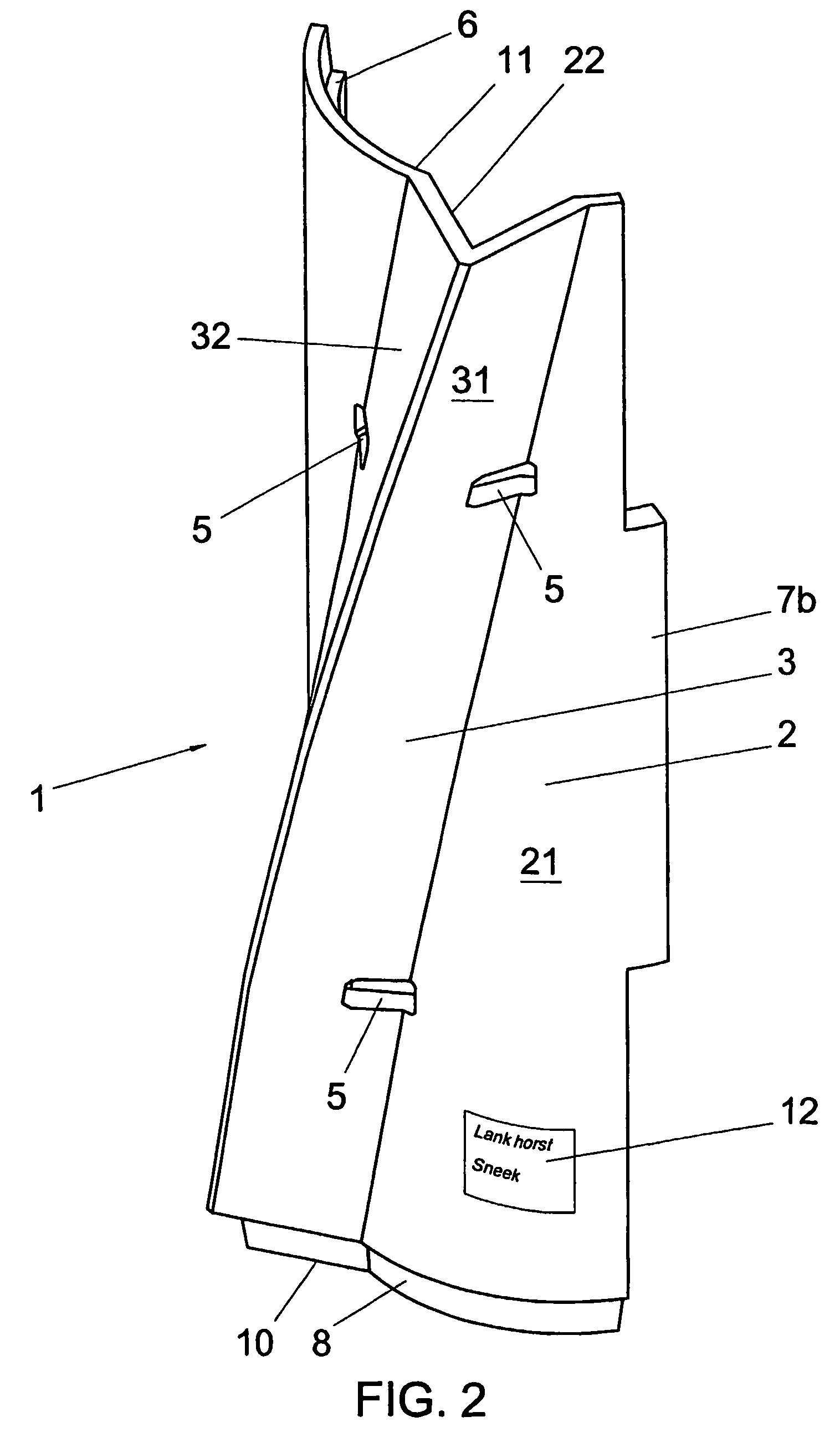
[0015]The example of a suppression element 1 according to the invention, shown in FIGS. 1-3, has an envelope 2 with an exterior 21, which, in use, faces away from a tubular element, not shown, which, in use, is partly enveloped by the element 1. On the exterior 21, the element 1 has a projection 3 pointing away from the envelopes, which reduces the formation of vortices on the downstream side of the tubular element. In the shown example, the projection is fin-shaped and has a triangular cross-section, the fin faces 31, 32 forming two sides of the triangle. The projection extends in the longitudinal direction A of the element 1 and lies at a non-right angle to the longitudinal direction, so that, as shown in FIG. 4, the projections of several elements coupled to each other are together spirally or helically shaped.

[0016]In the shown example, the suppression element according to the invention is modular. The shown example of a suppression element is, seen in the circumferential direct...


PUM


Abstract

A suppression element (1) for vortex vibrations, comprising an envelope (2) for t least partly enveloping a tubular element (100); at least one projection (3) pointing away from the envelope. The envelope is modular to form with similar suppression elements a tube (101,102), which, in operation, at least partly, envelops a tubular element (100). Also, a construction kit for a suppression system and a suppression system for vortex vibrations with at least two suppression element (1), which together form a tube, which in operation, at least partly envelops a tubular element (100), as well as an apparatus for extracting minerals with a pipeline enveloped by a suppression system are disclosed.

Description

FIELD OF THE INVENTION[0001]The invention relates to a suppression element for vortex vibrations.BACKGROUND OF THE INVENTION[0002]The invention also relates to a construction kit and an assembly of suppression elements and an apparatus for extracting minerals.[0003]Suppression elements for vortex vibrations are, for instance, known from the offshore industry as so-called ‘Vortex Induced Vibration Strakes’ or ‘VIV Strakes’. Such suppression elements are used on, for instance, offshore drilling platforms to reduce the forces exerted by the water on the pipeline running from the platform to the oil well or a so-called ‘off-loading vessel’. Owing to the flow of the water, the pipeline experiences a force, on the one hand because the water, because of flow, exerts a force on the upstream front side of the line, and on the other hand because on the downstream back side vortices arise, by which a suction force is exerted on the back side. The vortices on the back side can also cause vibrat...

Claims


Application Information

Patent Timeline
IPC IPC(8): F15D1/10B63B21/50E21B17/01F15D1/12
CPCB63B21/502B63B39/005F15D1/10E21B17/01B63B2021/504F16L1/123
Inventor ESSELBRUGGE, MARTINVAN BELKOM, ARNOLDUSZUIDHOF, WILFRED
Owner LANKHORST SPECIAL MOLDINGS
Why Eureka
Try Eureka