
Electron confinement inside magnet of ion implanter

a technology of ion implants and magnets, applied in the field of ion implants, can solve the problems of ion beam b>2/b> transport loss, ion beam b>2/b> productivity improvement, and achieve the effects of reducing electron losses, improving space charge neutralization, and improving the transport efficiency of a low energy beam

Active Publication Date: 2008-12-02
VARIAN SEMICON EQUIP ASSOC INC
View PDF8 Cites 2 Cited by
  • Summary
  • Abstract
  • Description
  • Claims
  • Application Information

AI Technical Summary

Benefits of technology

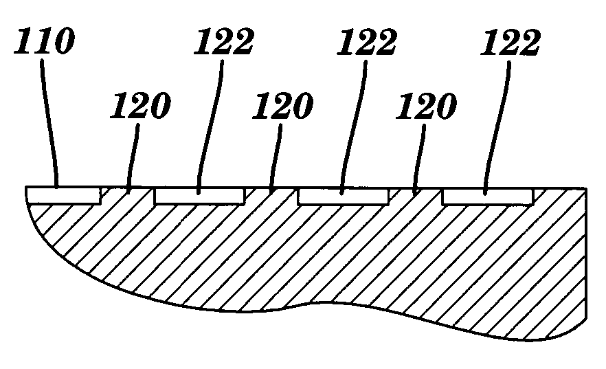
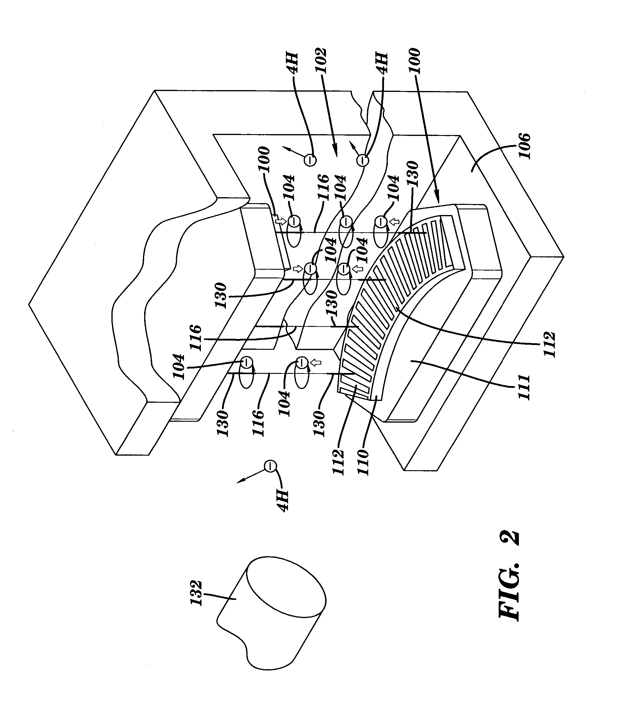
[0008]The invention includes a method and apparatuses for improving space charge neutralization adjacent a magnet of an ion implanter by confining the electrons inside a magnetic region thereof to reduce electron losses and therefore improve the transport efficiency of a low energy beam. The invention includes a magnetic pole member for a magnet of an ion implanter that includes an outer surface having a plurality of magnetic field concentration members that form magnetic field concentrations adjacent the magnetic pole member. Electrons that encounter this increased magnetic field are repelled back along the same magnetic field line rather than allowed to escape. The invention also includes an analyzer magnet and ion implanter including the magnet pole and a method of improving low energy ion beam space charge neutralization in an ion implanter.

Problems solved by technology

Improving productivity in ion implanters that use a low energy beam is a continuing issue in the ion implanter industry.
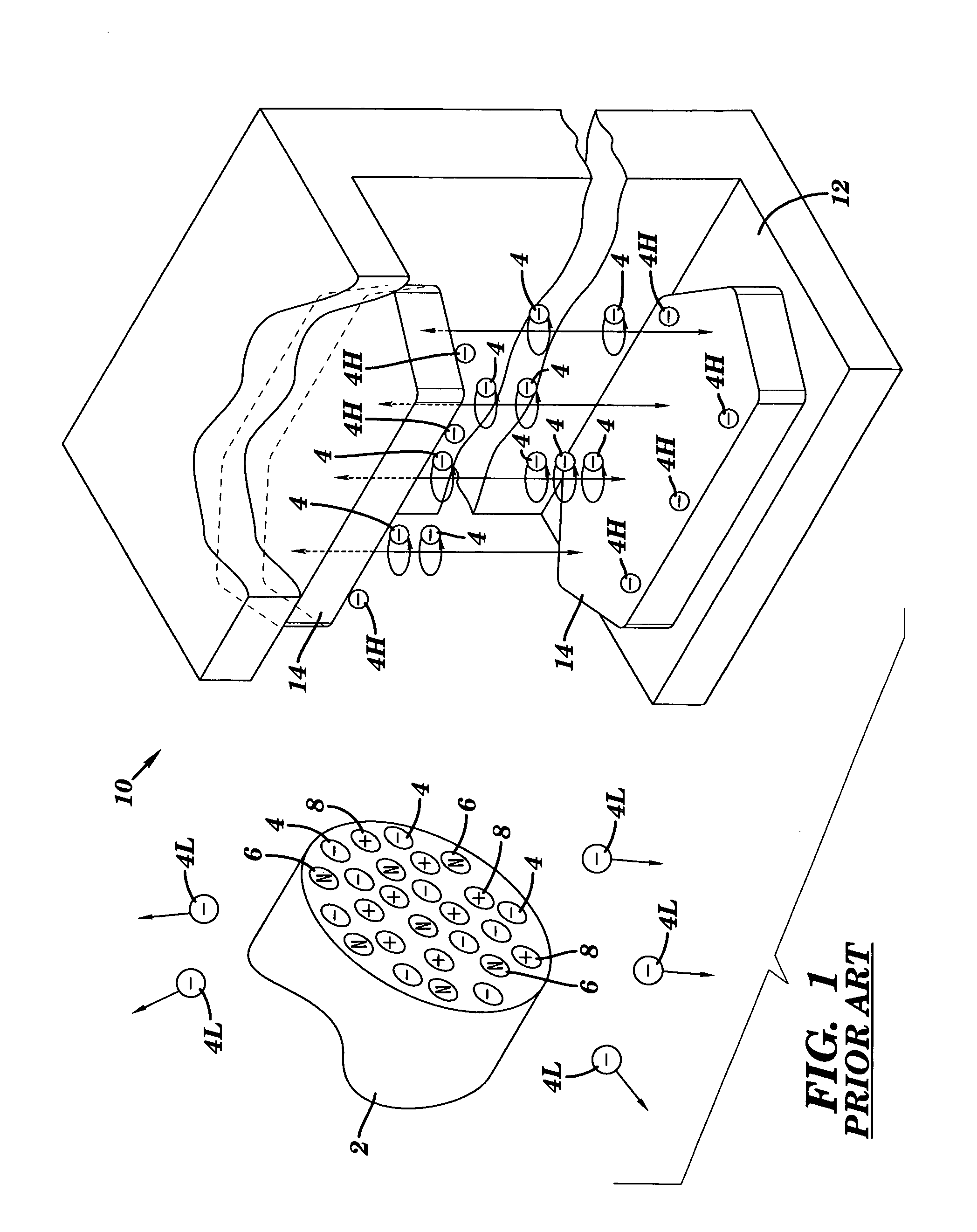
As an ion beam decelerates from high energy to low energy, the ion dispersion problem increases, which may result in the ion beam transport loss due to the repulsion.
This situation can lead to ion beam 2 expansion and further cause ion beam 2 transport losses if ion beam 2 generated electrons in magnetic region 10 are not adequate to replace lost electrons 4L.

Method used


Image

  • Electron confinement inside magnet of ion implanter
  • Electron confinement inside magnet of ion implanter
  • Electron confinement inside magnet of ion implanter

Examples


Embodiment Construction

[0023]With reference to the accompanying drawings, FIG. 2 illustrates a magnetic pole member 100 for a magnet 102 of an ion implanter according to the invention. As illustrated, magnet 102 is configured as an analyzer magnet. The coils of magnet 102 are not shown for clarity. It should be recognized, however, that the teachings of the invention as applicable to any magnet within an ion implanter. As shown in FIG. 2, magnetic pole member 100 is configured for mounting to an internal portion 106 of magnet 102. Magnetic pole member 100 includes an outer surface 110 that is, in one embodiment, raised from a base 111. Magnetic pole member 100 may be constructed of any now known or later developed magnetic material usable within a magnet 102.

[0024]Magnetic pole member 100 also includes a plurality of magnetic field concentration members 112 that form concentrated magnetic fields 130 (indicated by thicker magnetic field lines in FIG. 2) adjacent magnetic pole member 100. As best shown in F...


PUM


Abstract

A method and apparatus are disclosed for improving space charge neutralization adjacent a magnet of an ion implanter by confining the electrons inside a magnetic region thereof to reduce electron losses and therefore improve the transport efficiency of a low energy beam. A magnetic pole member for a magnet of an ion implanter is provided that includes an outer surface having a plurality of magnetic field concentration members that form magnetic field concentrations adjacent the magnetic pole member. Electrons that encounter this increased magnetic field are repelled back along the same magnetic field line rather than allowed to escape. An analyzer magnet and ion implanter including the magnet pole are also provided so that a method of improving low energy ion beam space charge neutralization in an ion implanter is realized.

Description

RELATED APPLICATIONS[0001]This application claims priority to U.S. Provisional Application No. 60 / 629,515, entitled “Electron Confinement Inside Magnet of Ion Implanter,” filed on Nov. 19, 2004, the contents of which are herein incorporated by reference in their entirety.BACKGROUND OF THE INVENTION[0002]1. Technical Field[0003]The present invention relates generally to ion implanters, and more particularly, to a method and apparatus for confining electrons inside a magnetic region of a magnet of an ion implanter.[0004]2. Related Art[0005]Improving productivity in ion implanters that use a low energy beam is a continuing issue in the ion implanter industry. One area of focus is improving beam transport efficiency. In particular, on single wafer ion beam implant systems, the ion beam is decelerated from high energy to low energy by an electrostatic bi-potential lens positioned before an analyzer magnet. An analyzer magnet functions to refine an ion beam by selecting appropriate ions f...

Claims


Application Information

Patent Timeline
Patent Type & Authority Patents(United States)
IPC IPC(8): H01J1/50
CPCH01J37/026H01J37/1475H01J37/3171H01J2237/055H01J2237/0041H01J2237/0042H01J37/317H01J37/36
Inventor RENAU, ANTHONYOLSON, JOSEPH C.CHANG, SHENGWUBUFF, JAMES
Owner VARIAN SEMICON EQUIP ASSOC INC
Learn More