Wiring component and magnetic recording drive for high data-rate recording

a technology of wiring component and magnetic recording drive, which is applied in the field of transmission system, can solve the problems of amplitude degradation, waveform degradation, and rise time degradation

Inactive Publication Date: 2008-12-02
WESTERN DIGITAL TECH INC
View PDF15 Cites 10 Cited by
  • Summary
  • Abstract
  • Description
  • Claims
  • Application Information

AI Technical Summary

Benefits of technology

[0013]Under such circumstances, it is a feature of the present invention to provide a wiring component enabled to generate overshooting required for high-speed data recording and enable high-speed data recording on a magnetic recording medium with simple design modification of the inter-connect substrate recording line, as well as to provide a magnetic disk drive that uses the same.
[0014]The above feature of the present invention is achieved effectively by a wiring component that includes a head element for recording / reproducing data on / from a recording medium, a recording and reproducing circuit for supplying a signal to be recorded to the head element and amplifying a signal to be reproduced by the head element, a first line provided at the recording and reproducing circuit side and used to connect the recording and reproducing circuit to the head element, and a second line provided at the head element side and used to connect the recording and reproducing circuit to the head element. A first recording line of the second line, which transmits the signal to be recorded, is divided into a first section for the recording and reproducing circuit side and a second section for the head element side while the second section has a portion of the first recording line, which has characteristic impedance that is lower than that of the first recording line of the first section and another portion of the first recording line, which has characteristic impedance matching that of the first recording line of the first section. If such a technique is employed, it becomes possible to fix the substrate of the second section provided at the head element side to the suspension on which the head element is to be mounted when the second line is formed on the substrate, as well as to lower the characteristic impedance by increasing the line in width. Consequently, overshooting required for high-speed data recording can be generated only with a simple modification of the design of the second line, thereby realizing high-speed data recording on a magnetic recording medium.

Problems solved by technology

In order to enable such faster recording in the magnetic disk drive, however, a signal current that rises quickly is required to be transmitted to the recording head by keeping the waveform and the following three points come up as problems.
The first problem is degradation of the rise time, the second problem is degradation of the amplitude, and the third problem is degradation of the waveform to be caused by ringing.
The first and second problems are mainly caused by a transmission loss in the object transmission system and the third problem is caused by a multiple reflection to be caused by impedance mismatching to occur among the parts of the transmission system.
Those problems are common not only to magnetic disks, but also to most of such magnetic recording media as magnetic tape, etc.
The method disclosed in the patent document 1 takes no consideration to the characteristic impedance of each section of the inter-connect substrate recording line, so that the method cannot avoid ringing to be generated in recording signals due to the multiple reflection to occur in each section of the inter-connect substrate recording line.
The method is thus almost disabled for accurate data recording.

Method used


Image

  • Wiring component and magnetic recording drive for high data-rate recording
  • Wiring component and magnetic recording drive for high data-rate recording
  • Wiring component and magnetic recording drive for high data-rate recording

Examples


first embodiment

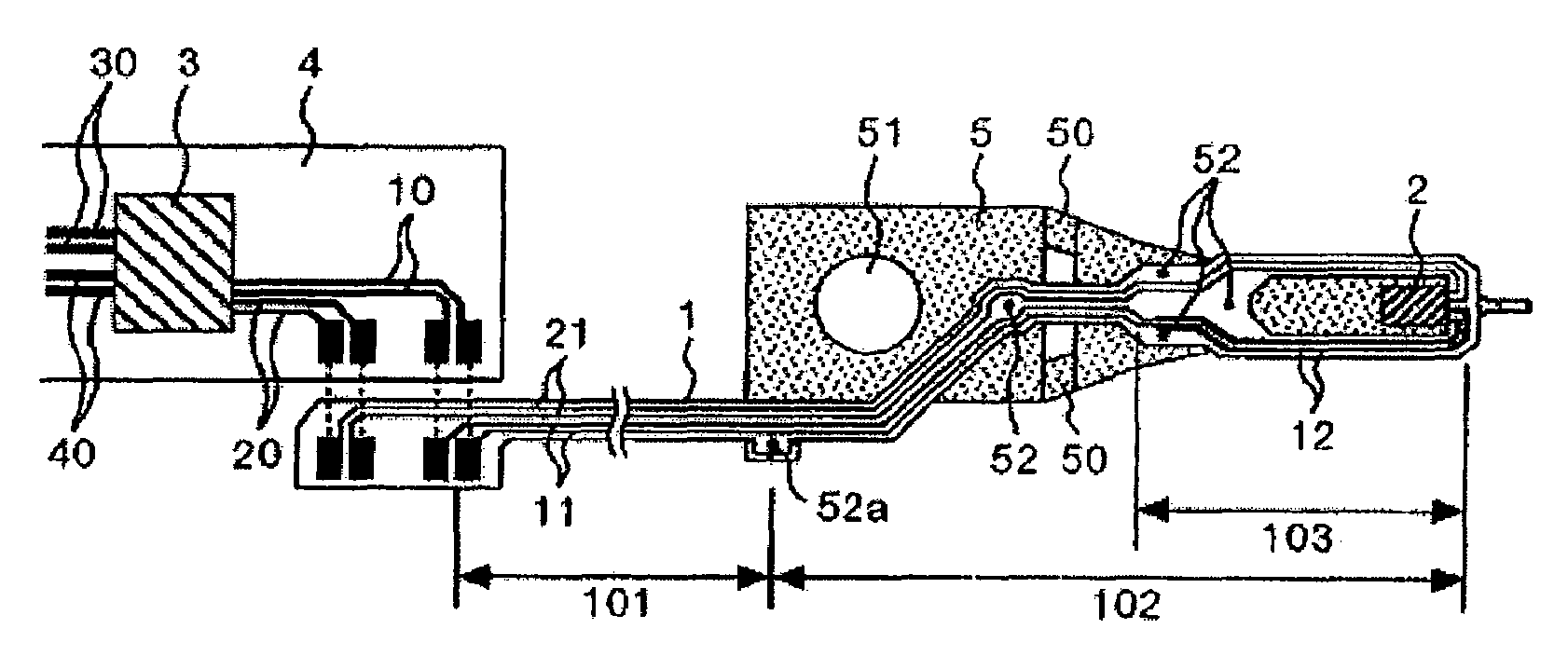
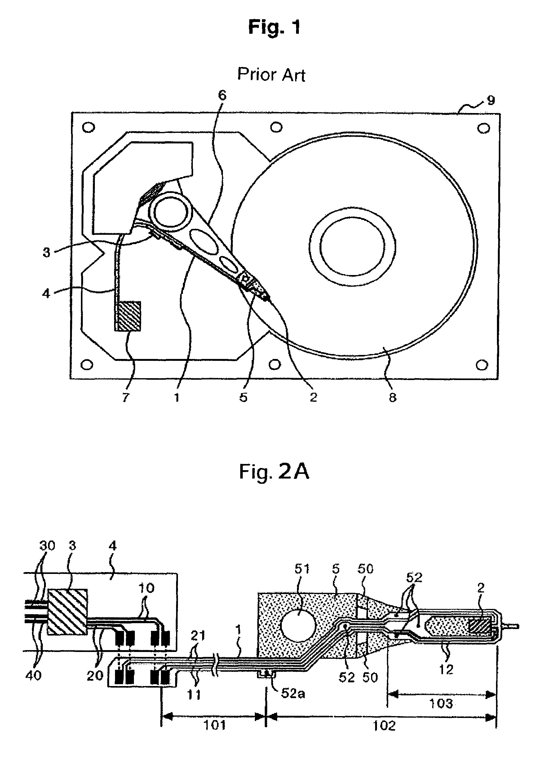
[0034]FIG. 2A shows the first embodiment of the wiring component of the present invention. A recording and reproducing circuit IC 3 is mounted on a main FPC 4 and the main FPC 4 is fixed to an arm 6 (FIG. 1) around the place where the recording and reproducing circuit IC 3 is to be mounted. Signals to be recorded / reproduced are exchanged between the recording / reproducing IC 3 and a signal processor LSI (to be described later) through a recording line 30 provided between the recording / reproducing IC 3 provided on the main FPC 4 and the signal processor LSI and through a reproducing line 40 provided between the recording / reproducing IC 3 and the signal processor LSI.

[0035]An inter-connect substrate recording line (first recording line) 11 is provided in the first section 101 between an end of the inter-connect substrate 1, which is the closest to the recording / reproducing IC 3, and a fixing position 52a closest to the recording / reproducing IC 3 among plural positions at which the inte...

second embodiment

[0076]In this second embodiment of the present invention, the inter-connect substrate recording line 11 increases in width slightly while the structure in the first embodiment is employed almost as is to set the characteristic impedance Z1 at 87Ω. As to be described later, in the first embodiment, if the data rate is 1 GBps, some ringing occurs due to the multiple reflection just after a peak. The ringing in such a case is not recognized as a trouble in general recording media. In some recording media, however, such ringing is required to be suppressed. This second embodiment corresponds to such a case.

[0077]If the characteristic impedance Z1 is set at 87Ω, a relationship Rs=Z0>Z1>Z2>Rh is satisfied, since the output resistance of the recording / reproducing IC 3 becomes Rs=100Ω, the characteristic impedance of the main FPC recording line 10 becomes Z0=100Ω, the characteristic impedance of the inter-connect substrate recording line 11 becomes Z1=87Ω, the characteristic impedance of th...

third embodiment

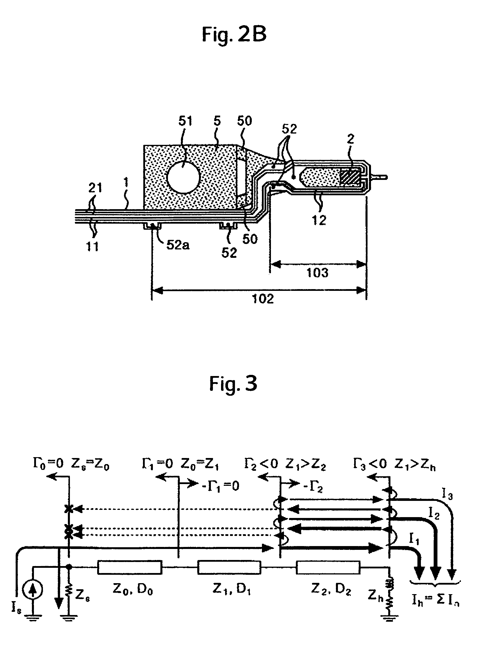
[0093]FIG. 13 shows the third embodiment of the wiring component of the present invention. In this third embodiment, an inter-connect substrate 1 is disposed aside from a spring part 50, not in the center of the spring part 50 in the second section 102 and an inter-connect substrate recording line 12 is extended up to a fixing position 52a closest to the recording / reproducing IC 3 among plural fixing positions at which the substrate 1 is to be fixed to a suspension 5 except for one side of the spring part 50. In other words, the inter-connect substrate recording line 12 provided in the second section 102, which is located between the fixing point 52a and the head element, is divided into two parts and disposed except for the fourth section 104 in parallel to the direction in which the spring part 50 of the suspension 5 goes to the head 2 from the arm fixing hole.

[0094]An inter-connect substrate recording line 12b provided in the fifth section 105 closer to the recording and reproduc...


PUM

PropertyMeasurementUnit
lengthaaaaaaaaaa
lengthaaaaaaaaaa
impedance Z1aaaaaaaaaa

Abstract

Embodiments of the invention enable high-speed data recording on a magnetic recording medium. In one embodiment, a first section is provided at the recording and reproducing circuit IC side of the inter-connect substrate while a second section is provided at the head side and a third section is provided between a position closer to the head than a section crossed by a spring part of the suspension and the head. Then, the characteristic impedance of the third section recording line is set lower than that of the recording line in the second section except for the first and third sections and the wiring distance between the recording line and the reproducing line in the third section is set longer than that between the recording line and the reproducing line in each of the first and second sections. In addition, the output resistance of the recording and reproducing circuit IC is equated with the characteristic impedance of the main FPC recording line.

Description

CROSS-REFERENCES TO RELATED APPLICATIONS[0001]This application claims priority from Japanese Patent Application No. JP2005-017830, filed Jan. 26, 2005, the entire disclosure of which is incorporated herein by reference.BACKGROUND OF THE INVENTION[0002]The present invention relates to a transmission system provided between a recording and reproducing circuit and a head element in a magnetic recording drive and more particularly to a wiring component preferred to record high-speed data signals and a magnetic recording drive that uses the same.[0003]The patent document 1 (Official gazette of JP-A No.57549 / 2000) discloses a method for lowering the inductance to shorten the rise time of a high-speed signal current waveform in a magnetic disk drive by forming both of an inter-connect substrate recording line and an inter-connect substrate reproducing line wider partially at all regions except around the head element. And, the patent document 2 (Official gazette of JP-A No.202601 / 2001) dis...

Claims


Application Information

Patent Timeline
Patent Type & Authority Patents(United States)
IPC IPC(8): G11B5/48
CPCG11B5/486
Inventor OKABE, HIROSHI
Owner WESTERN DIGITAL TECH INC
Why Eureka
Try Eureka