
Pacing with hemodynamic enhancement

Inactive Publication Date: 2008-12-02
IMPULSE DYNAMICS NV
View PDF187 Cites 64 Cited by
  • Summary
  • Abstract
  • Description
  • Claims
  • Application Information

AI Technical Summary

Benefits of technology

[0019]It is an object of some aspects of the present invention to provide methods and devices for pacing the heart with enhanced contractility of the heart muscle.

Problems solved by technology

Furthermore, it is known in the art that the use of a pacemaker generally results in decreased contractility of the cardiac muscle and, consequently, a decreased cardiac output (CO) for a given heart rate.
This, of course, causes a major problem for the patient, since a demand for a higher pacing rate typically stems from a demand for an increase in tissue oxygen supply.
Research and clinical experience show that with various types of pacemakers, some cardiac output augmentation may take place initially, but is not maintained on a long-term basis and may even deteriorate compared to the situation before beginning pacing.
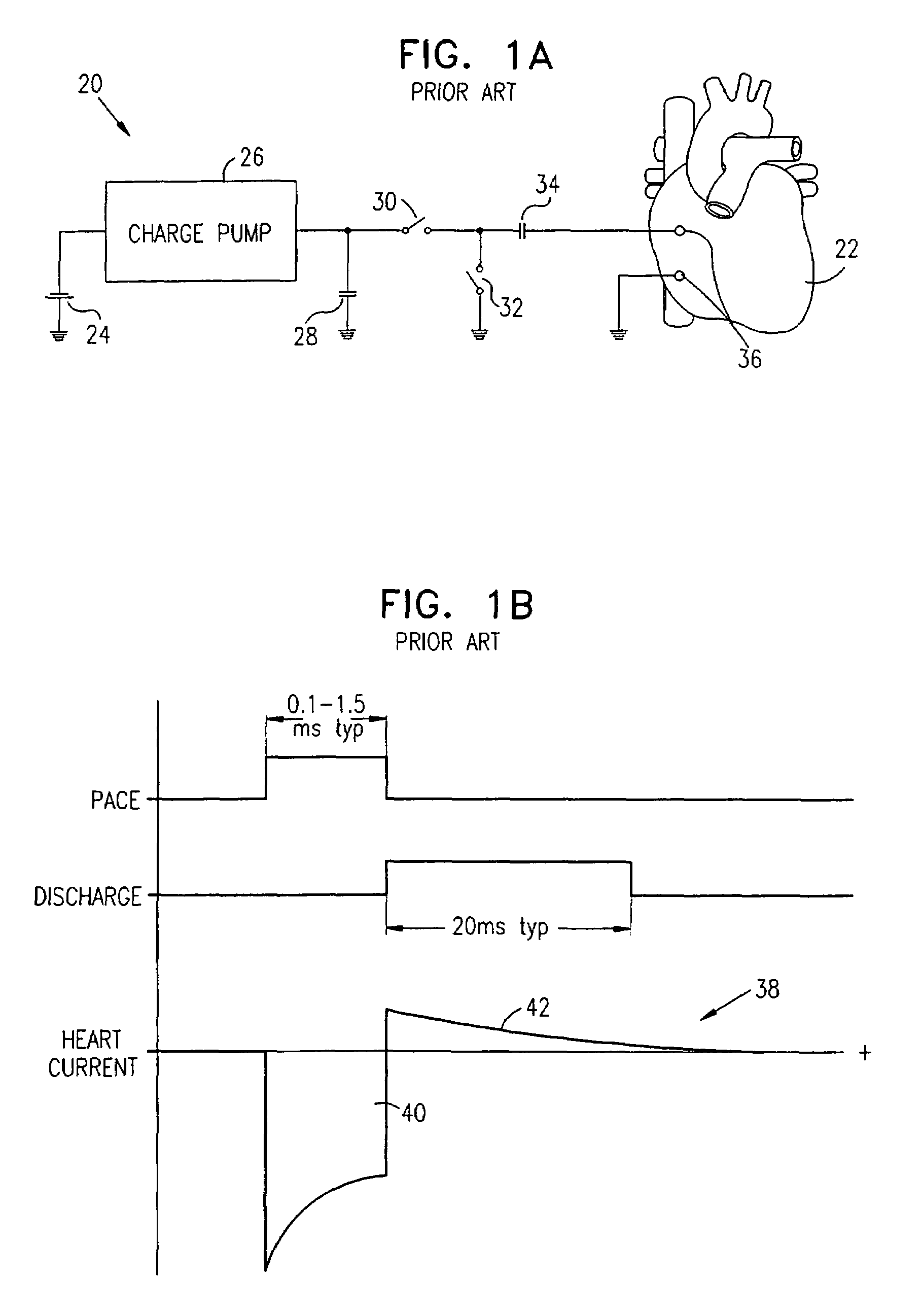
A longer duration or higher amplitude has been considered undesirable, because it would tend to discharge battery 24 prematurely without any improvement in the pacemaker performance or in the physiological performance of the heart or the safety of the pacing.
The specific duration and amplitude of this phase of the pacing waveform are not significant from the point of view of pacing, since it is intended only to remove residual charge and does not provide any stimulation to the heart.

Method used


Image

  • Pacing with hemodynamic enhancement
  • Pacing with hemodynamic enhancement
  • Pacing with hemodynamic enhancement

Examples


Embodiment Construction

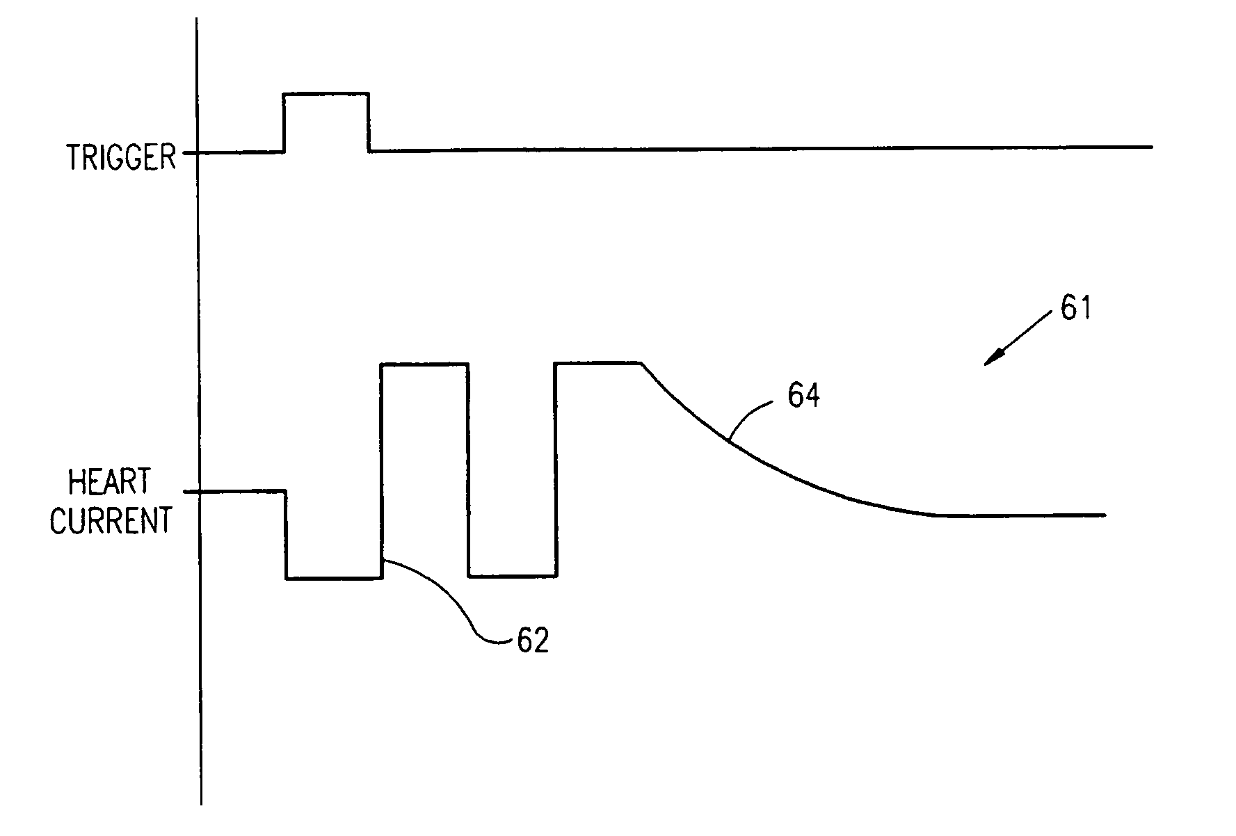
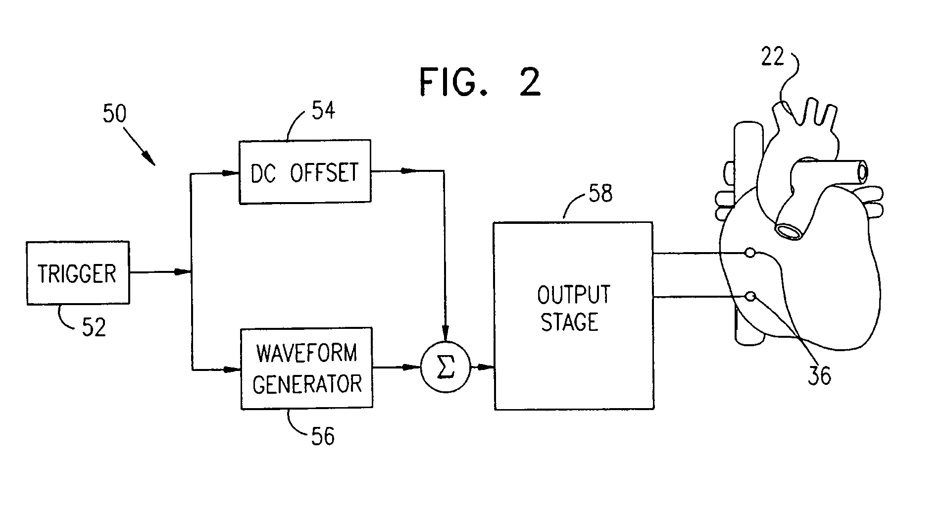
[0099]Reference is now made to FIG. 2, which is a schematic block diagram illustrating a pulse train generator 50, which generates and applies extended pacing signals to heart 22 via electrodes 36, in accordance with a preferred embodiment of the present invention. Generator 50 is preferably used as part of a complete pacing system (shown below in FIG. 6), but it has also been used by the inventors in experimental assessment of the principles of the present invention, as described hereinbelow with reference to FIGS. 4 and 5.

[0100]Generator 50 comprises a waveform generator 56 and, preferably, a DC offset generator 54, which are synchronized by a trigger generator 52. The outputs of the waveform and DC offset generators are summed and input to an output stage 58, which preferably comprises a voltage output stage or, alternatively, a voltage-to-current converter. Trigger generator 52, waveform generator 56, DC offset generator 54 and output stage 58 comprise electrical elements that a...


PUM


Abstract

Apparatus (170) for heart pacing with hemodynamic improvement, including one or more electrodes (36), which convey electrical signals to respective cardiac muscle segments. Signal generation circuitry (50) applies an extended pacing signal (60, 61), having an overall duration greater than three times a chronaxie time, to the one or more electrodes so as to pace the heart. The signal preferably includes a train of a plurality of biphasic pulses, and has an amplitude at least three times as great as a threshold for pacing the heart, but not sufficient for cardioversion.

Description

FIELD OF THE INVENTION[0001]The present invention relates generally to cardiac therapeutic devices, and specifically to cardiac pacemakers.BACKGROUND OF THE INVENTION[0002]In certain heart diseases, either congenital or acquired, natural pacing is replaced or assisted by artificial pacing induced by a pacemaker, which is generally implanted in the patient's chest. Pacemakers known in the art provide artificial excitatory pulses to the heart tissue to control the heart rhythm. Early pacemakers were asynchronous pulse generators that operated at a fixed invariant rate. Later, demand type pacemakers were developed, in which stimulation pulses are produced only when a naturally-occurring heartbeat is not detected within some maximum type period.[0003]Cardiac pacemakers are required to deliver a stimulus pulse of sufficient magnitude and duration to cause an action potential to propagate from the point of excitation, leading to heart muscle contraction. Thus, the primary function of a pa...

Claims


Application Information

Patent Timeline
IPC IPC(8): A61N1/362A61N1/05A61N1/365
CPCA61N1/362A61N1/3627A61N1/36167A61N1/36178
Inventor DARVISH, NISSIMFELSEN, BELLASHEMER, ITZIKKORNFELD, JUDITH
Owner IMPULSE DYNAMICS NV
Learn More